holographic photoelasticimetry & stress analysis*)
jean-charles viénot
university of besancon, faculté des sciences et des
techniques, france
in the early times of holographic interferometry we prepared a christmas card (fig.1). that was in 1965. we thought then it was easy to measure the strain resulting from any stress, in particular in a photoelastic model, much more simple than our three jaw chuck. it was not so. and the picture was used as a potter an the occasion of the symposium on holography, held in france in 1970.
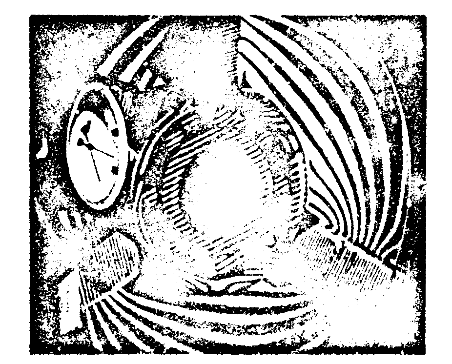
fig.1.
indeed, as forces are applied to a photoelastic model, they produce deformations in the body which also becomes birefringent. it is known that the rapid and slow axes coincide with the principal direction of the stresses. linear relationships hold between the principal indices n1, n2 of the birefringent material and principal stresses
σ1 and
σ2. they are the maxwell stress option law,
in conventional photoelasticimetry one places the model between crossed polarizers, and looks at the resulting interference pattern. one then observes:
- isocline lines, which correspond to the directions of the principal stresses;
- isochromatic linee, which correspond to the difference between the principal stresses, σ1-σ2 (fig.2).
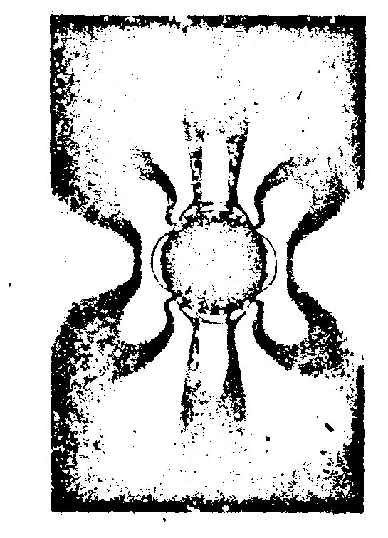
fig.2.
a supplementary experiment is necessary to measure σ1 and σ2. for instance one can determine the sum σ1+σ2, which corresponds to the so-called isopachic lines.
in a holographic method, we illuminate the model with nonpolarized light (fig.3). so, we consider 2 directions correspon-
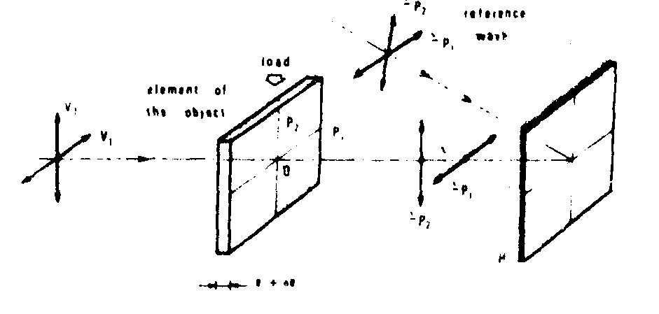
fig.3.
ding to the principal axea respectively. note that the incident light can also be circularly polarized. we then record a hologram: the calculation (fig.4) shows the existence of the isochromatic lines in the reconstruction.the phenomena are observed
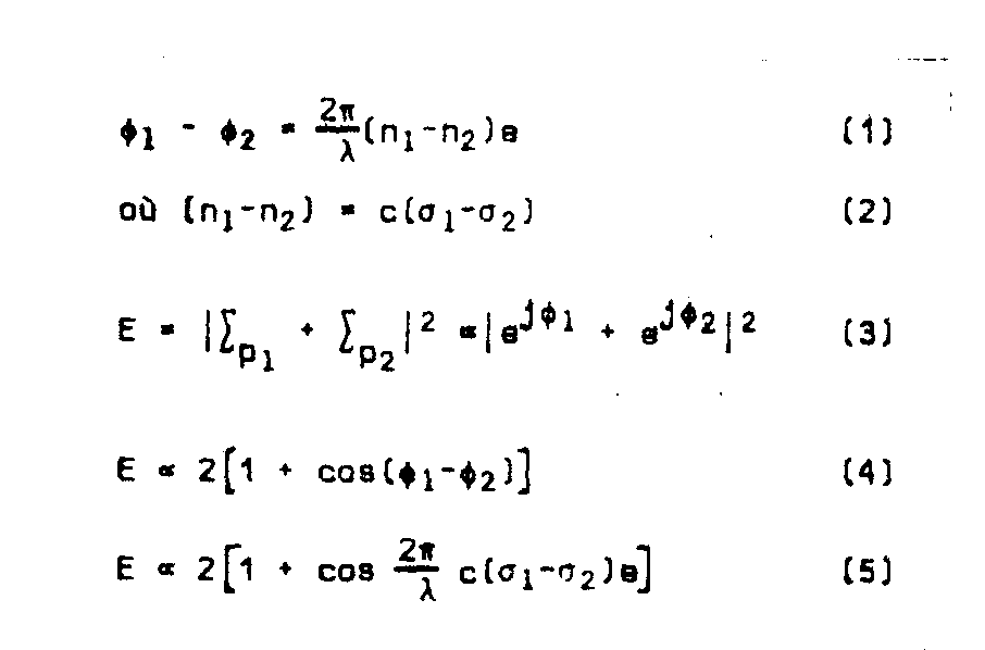
fig.4.
in white light. fig.5 shows a comparison between classical results (left) and holographic results (right). in white light,the visibility is then a function of
σ1-σ2 as show in fig.6 (eq.4).
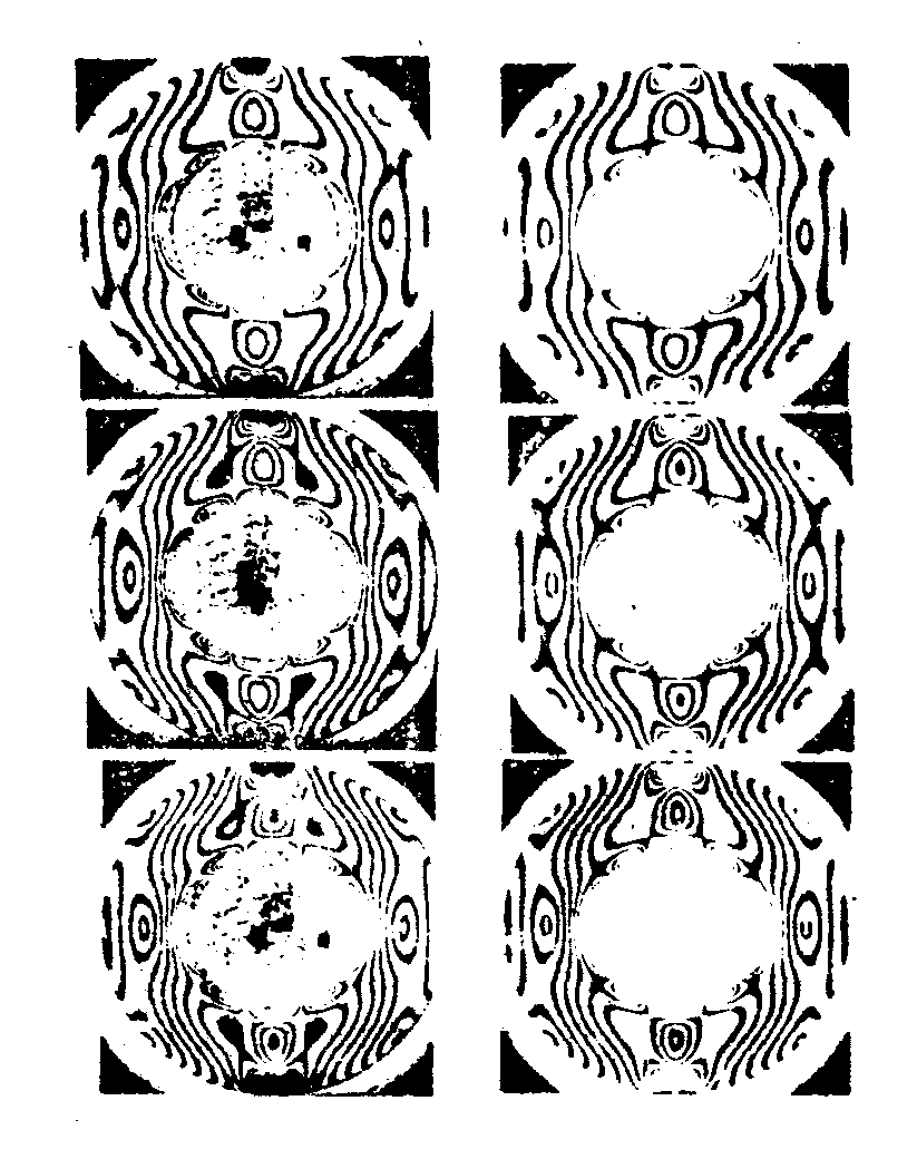
fig.5.

fig.6.
this illustrated by the dark fringes you can see now, in the spectrum of the reconstruction white source (fig.7).
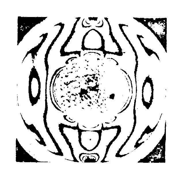
fig.7.
how to see the isopachic lines?
the fractional deformation of the model in also directly related to the sum
σ1+σ2 of the principal stresses. therefore, if the model was not birefringent, one could observe the contour, lines along. unfortunately, if we proceed to a double - exposure experiment (1st exposure before the force is applied; 2nd exposure after application of the force), the 2 patterns are supepposed (fig.8).
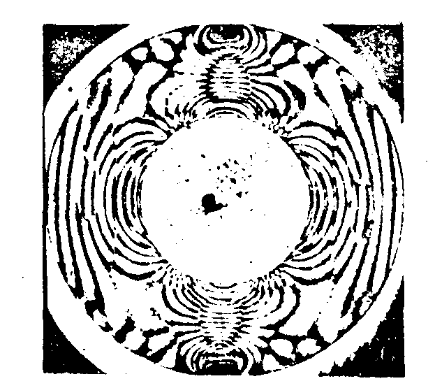
fig.8.
one needs then to make non-observable one pattern at a time-without destroying it. this is the technique (fig.9): after passing through the model we rotate the polarisation plane by a 90° angle. the vibration comes back, again through the model; thus the phase difference is cancelled. this is made by means of a faraday-cell (magnetic effect).

fig.5.
the next picture ahowa the isopachic lines alone on one side (fig.10) then the isochromic/iospachic lines together.
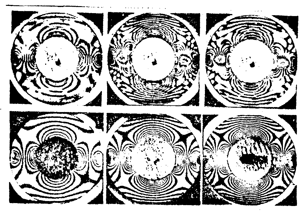
fig.10.
at the reconstruction the intensity in the images ia described by a simple calculation (fig.11).
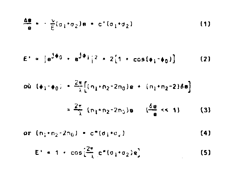
fig.11.
the lines which appear outhe model represent the isopachic lines (fig.12). as before it can be sizown that obgervation is possible in white light.
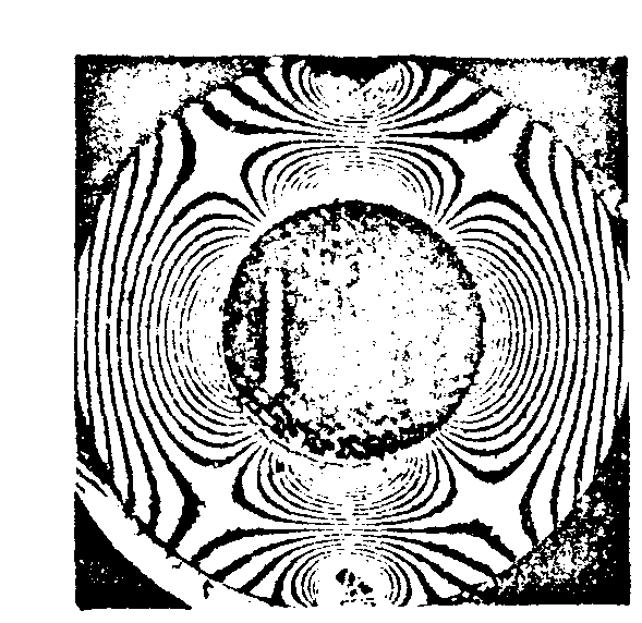
fig.12.
now, if we use 2 reference beams at the recording stage, the angle between them being large enough to avoid interference effects, we obtain the 2 sets of fringes with one hologram only. this is the technique:
isopachic (-1st recording before loading (refrence beam n°1)
lines (
alone) -2nd " after " ( " n°1)
isochromatic ( -3rd " no change in loading " n°2)
lines )
alone(
a result is given in our 1972-christmas card (fig.13): top: both sets of lines;
bottom left: isopachic lines, rights isochromatic lines.
note that the diachroism of the nirrors sometimes yields isoclines.
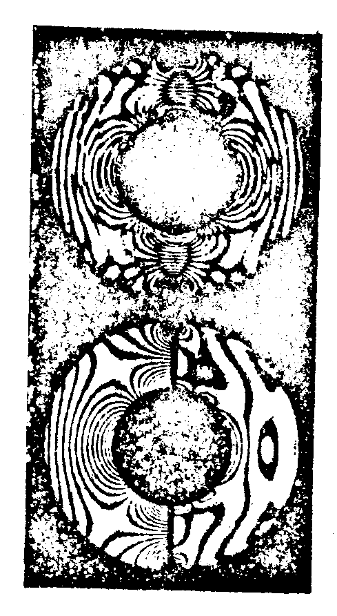
fig.13.
a picture of the apparatus ia given now (fig.14), but the complete seting is a little bit complicated (fig.15).
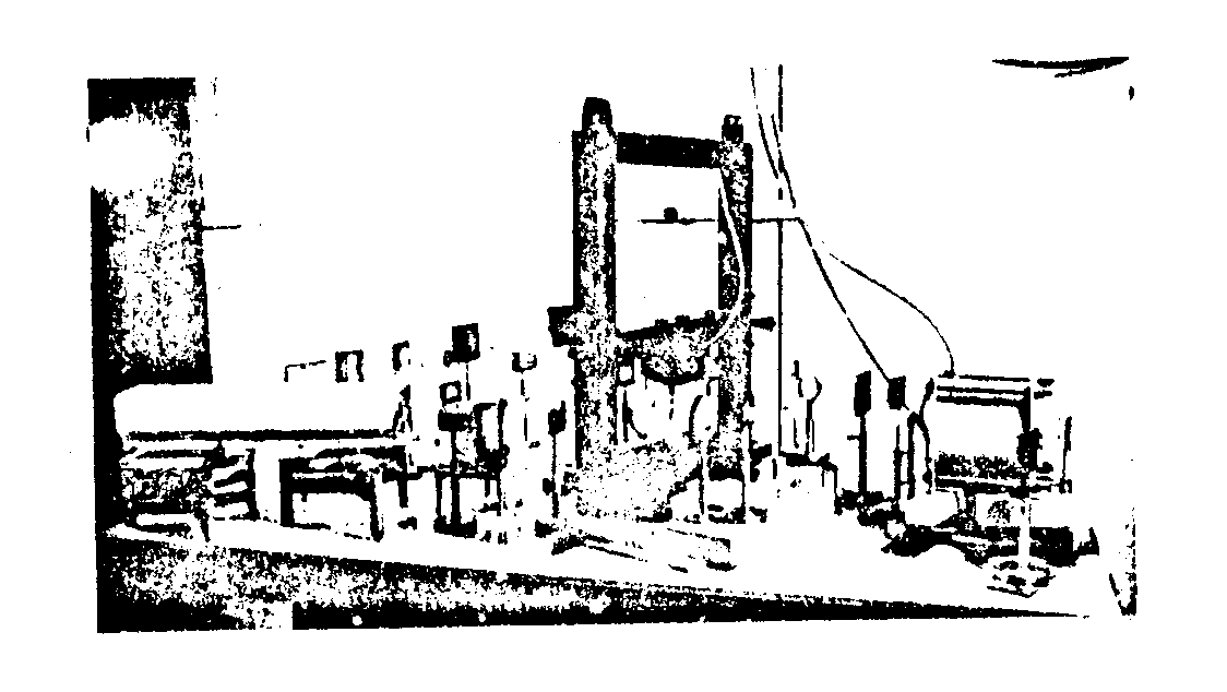
fig.14.
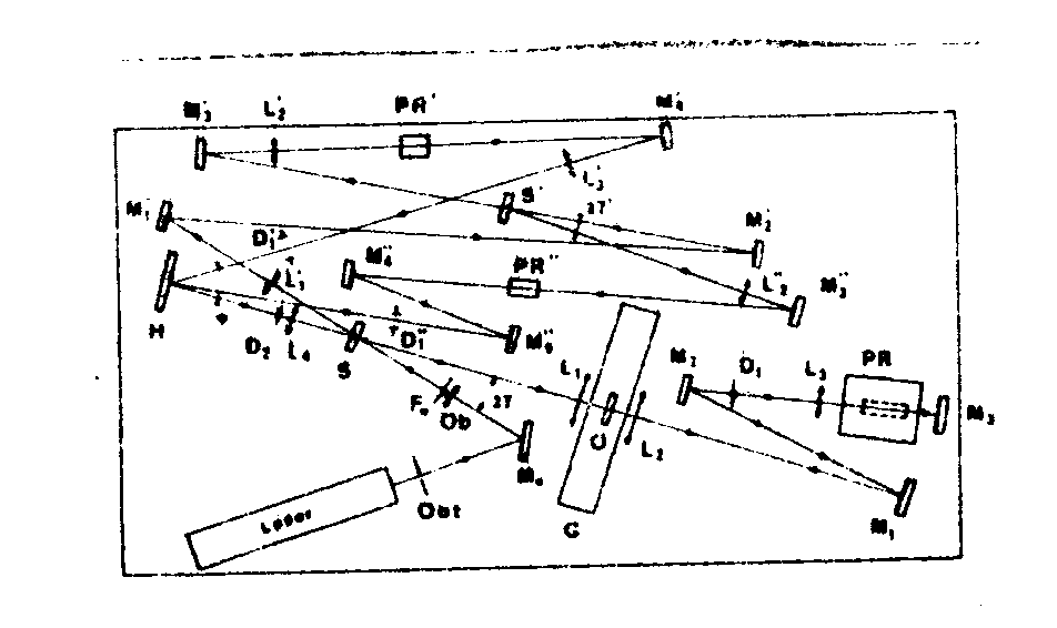
fig.15.

