.
the treatment is too lengthy to be discussed here; the paper also contains many basic proofs of theorems. the following cases are treated; a circular, a rectangular, and a crating aperture. how localization is treated is shown in fig.1 for the simplest of the cases. that the localization is largely dependent on the position of the entrance aperture is seen in fig.2 - here, it is on finite distance. this is due to the fact that the lateral shifts of the reflected field and its lateral correlation length determine the v values, and since the correlation length depends on the angles. it is thus the variation of angular aperture with focal siting which accounts for the diffe rence. due to the asymptotic behavior of the visibility high-contrast fringes are seen at a great distance, which is not the case for a distant entrance pupil. as just one example of the experimental verifications of the theories, fig.3 is shown whicli corresponds to the case of finite entrance pupil just referred to.
walls has, in a later article /2/, more related these phenomena to the concept of homologous rays introduced by viénot et al. this has made it possible to present fringe spacing and fringe localisation in a very simple geometrical picture. in relation to viénot's first introduction of the concept for surface movements coplanar with the illumination and observation directions, it was here extended to more general movements, including strain and shear.
we had karl a.stetson in our laboratory for about 2 years and very greatly benefitted from his ability and scientific imagination. as well known, r.l.powell and he in 1964 discovered hologram intarferonetry which, since, lias been one of the most important of the applications of holography. with nils-erik molin a series of interesting papers were published during and after this time.
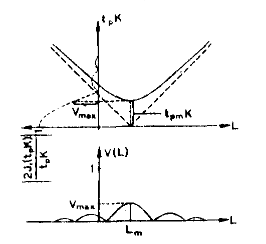
fig.1. variation of the visibility, v, as function of the distance l along the prinoipal ray for a circular aperture. the upper diagram represents the variation of a certain argument tpk with l. this factor t k is carried into the dotted 2j1(x)/x function at the left, and the value of this function is carried to the lower diagram. the value of tpmk determines whether the visibility is high enough for fringes to be seen. k is proportional to the aperture radius.

fig.2. variation of the visibility,v, as a function of l, but on the contrary to fig.1, at a finite distance along the ray, lp from the object's mean surface. there is an asymptotic visibility which has no analogy in fig.1.
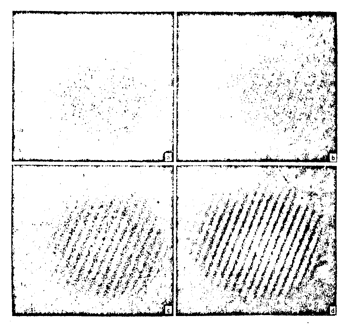
fig.3. experiments showing the visibility variation for a finite entrance pupil according to fig.2, a - d are for increasing l, and the results are in qualitative agreement with theory.
two or three of these paper will be discussed here.the first /3/ is a two-part paper. it gives the careful experimental verification of earlier theoretical work by stetson. this theory gives a unified description of the fringes of hologram interferometry regardless of the temporal or geometrical nature of the motion. it is well known, for example, that in double exposure hologram recordings, object displacements cause the reconstruction of sinusoidal fringes while in hologram recordings of vibratory
motion, they cause zero order bessel function fringes. it is also well known that if the object surface reflects light diffusely, the fringes in either case will be localized, i.e. visibility of the fringes will have a maximum over same contour in space. the unified theory cited predicts that both the geometrical loci of the fringes and their regions of localization should be the same for equivalent vibratory and two step motions, regardless of the temporal nature of the motion. this was one of the primary issues to be verified by this study, and accordingly the experiments were designed for accurate duplication of the same geometrical motion either as vibration or as two discrete positions.
another lasue of considerable importance to applications of the theory was that it had been formulated in terms of only a plane surface illuminated by a parallel beam of light. in particular it was important to leam experimentally if if modifications should be made to the theory to account for curved object surfaces or curved illumination beams, especially with respect to localisation conditions. accordingly experiments were made on objects consisting of three diffuse surfaces: concave, flat and convex, and on flat surfaces illuminated in part with coilimated light and in part with divergent light.
three types of motion v/ere studied: pivot motion, in-plane rotation, and in-plane translation. for each type of motion, the rigorous equations of the general formulation are reduced to formulas directly applicable to the geometries of the experiments. to insure freedom from system instabilities and to allow comparison between double exposure and vibration fringes, time average holograms were used rather than real-time hologram interferometry. the measurement of the fringes and their localization was made on the real Image of the conjugate reconstruction of the hologram.
for the pivot motions, the results are given in fig.4, a -h. the object consisted of three surfaces, the upper convex of 100 mm radius, the middle flat, and the lower concave of 100 mm radius.
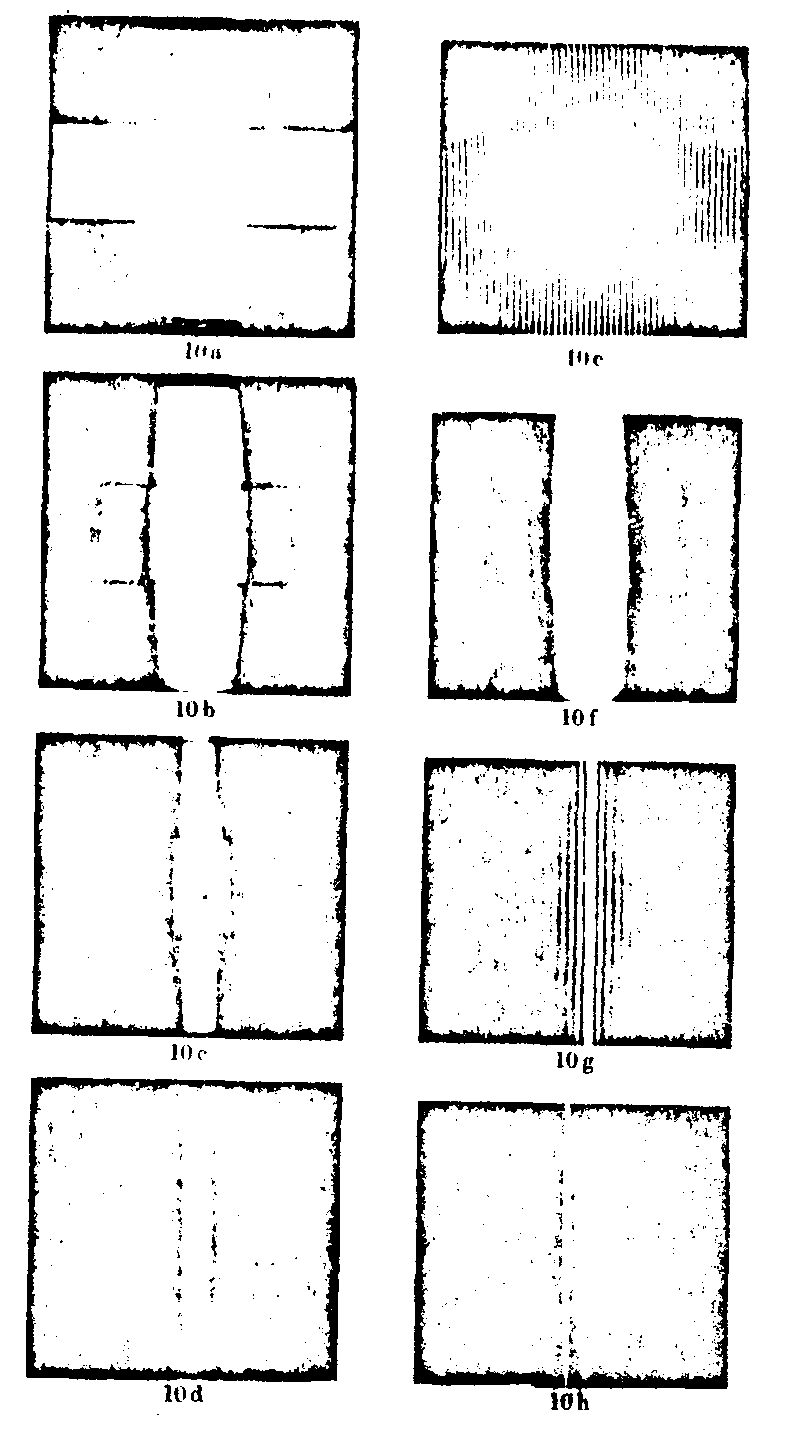
fig.4. recordings in the real Image fields for four hologram recordings of pivot motion for an object with three surface curvatures. for details and comparisons with calculation, see the text in the original paper.
they are all in conformance with the theory, even quantitatively as shown from fig.5, which is just one sample from the material.
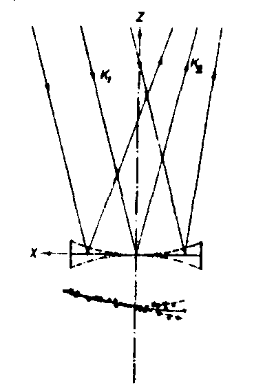
fig.5. a plot of the calculated fringe planes for pivot motion of the three surface curvatures and comparisons with data points. (lines solid for the flat surface, dashed for the concave surface, dot-dashed for the surface).
important conclusions were drawn from three experiments, one of them that a correction must be introduced when not collimated but curved illumination is used. these results stress the importance that all geometrical data are given for the rigorous interpretation and evaluation of hologram interference fringes.
a continuation of this work is given in a paper the year after by the same authors /4/. here, fringe loci and localisation were examined for mutually independent and dependent rotations of an object around two non-intersecting orthogonal axes. it was established that independent motions can be observed independently since their corresponding fringe sytema have independent localization properties. with mutually dependent vibrations a potentially useful property of fringe localization was found, namely that temporally orthogonal vibrations could be resolved. the
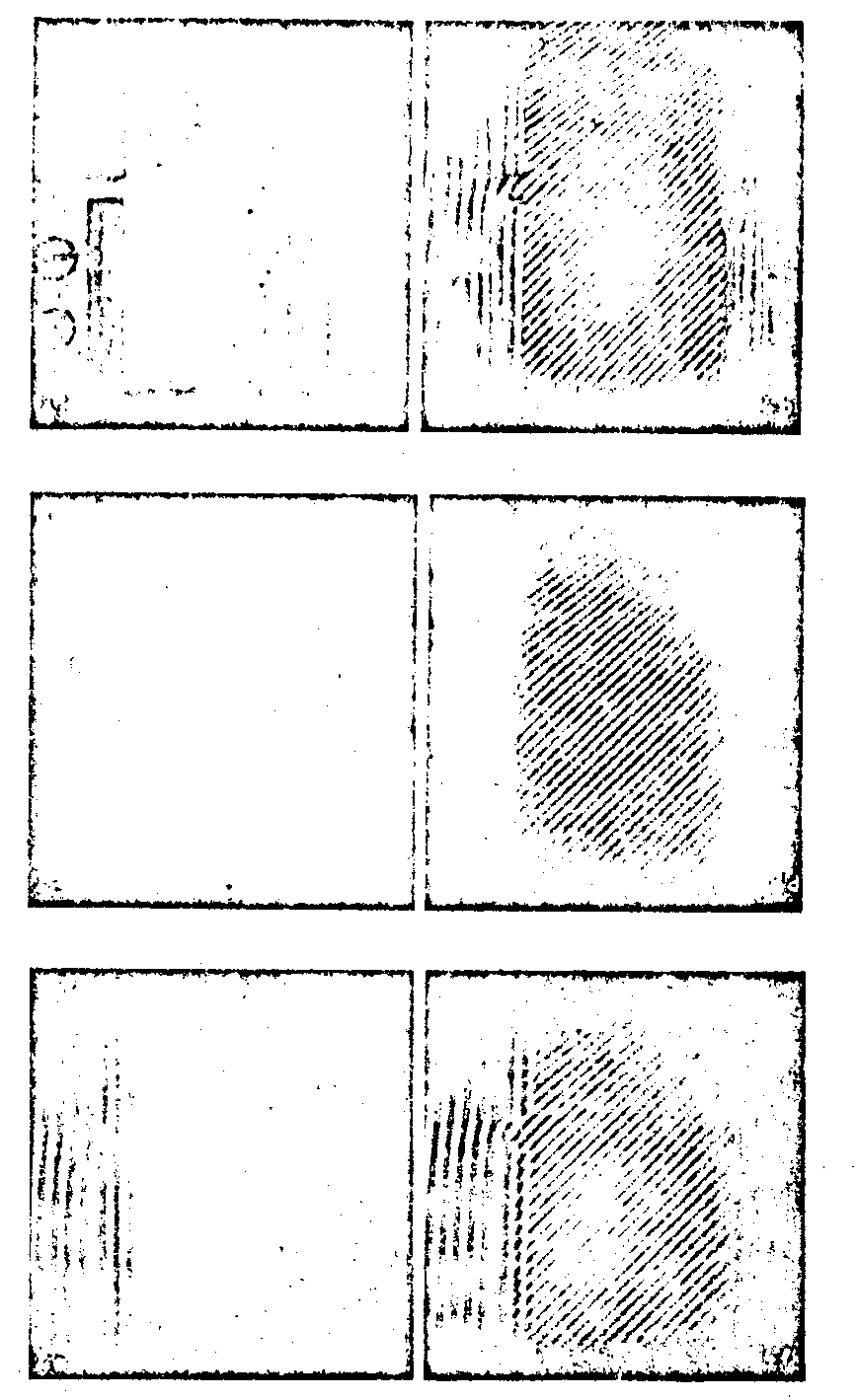
fig.6. reconstructions from one hologram having recorded simultaneous discrete rotations. the hologram was made by a double exposure, between which both rotations were applied. 4a, 4c, and 4e were recorded with the full aperture of the hologram when reconstructing the Image, while 4b, 4d, and 4f were recorded with three orientations of a slit aperture in the plane of the hologram. 4a and 4b show the object plane, 4c and 4d show a plane 1.5 cm behind the object plane, and 4e and 4f show a plane 3.0 cm behind the object plane. the orientations of the slits in 4b, 4d, and 4f are vertical, 45° and normal to the fringes, and horizontal, respectively.
fringes have high visibility where the zero-order fringe of one component intersects the localization plane of the other and vice versa. the role of a slit aperture in determining localisation planes of fringes is shown.
just as an example, fig.6 contains reconstructions from one hologram having recorded sinultanaous discrete rotations.
fig.7 gives condensed results from calculations and findings, in a self-explanatory way. the formulas are taken from an earlier publication of stetson.
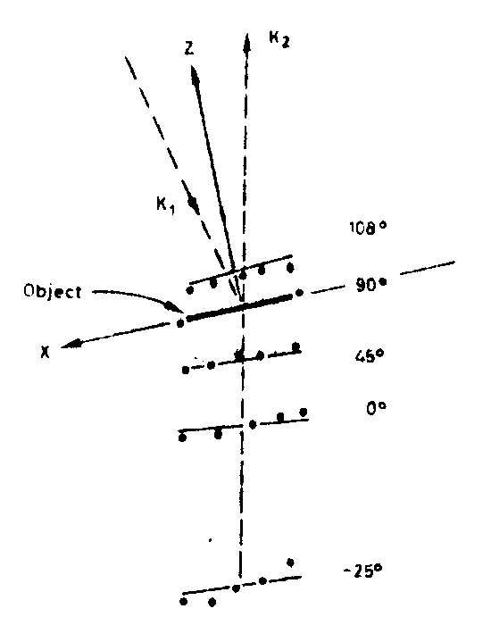
fig.7. measurement of slit aperture localitation planes for the hologram of fig.6. solid olroles show data points for planes of high fringe visibility for 5 orientations of a slit aperture. the thin solid lines show corresponding calculations.
time-average observation in real-time hologram
intorferometry by use of rapid in-suti processing
in this printed version of the lecture, in order to save space i refer to the most important of the papers, namely, by k.biedermann and n.e.molin /5/. it is a very complete paper, with good photographs of holograms of vibrating objects, and referring it briefly would not do justice to it. its abstract reads:
a rapid in situ processing system for holograms to be used in real-time hologram interferometry is designed. the plates are held in a liquid gate and exposed under immersion in the developer. interferometric evaluation takes place with fixing bath surrounding the plate.the swelling properties of photographic layers are discussed, and formulae are given for a rapid developer and a fixing bath of the same index of refraction, which are matched to keep the layers of agfa-gevaert scientia 8e70 and 10e70 plates at the same thickness in both solutions. an instruction is given on how to match processing solutions by checking the fulfillment of the bragg-angle condition. the volume character of these thick holograms suppresses inter-modulation noise, making practicable high modulation and a reference source close to the object. because of hypersensitization, exposure time is reduced by a factor of 2-3. interferometric evaluation can start 100 - 180 s after exposure. fringe-free superposition of the object field and the reconstructed field is obtained, allowing tine-average observation of vibrations in real time by visual inspection or photography. interferograms are shown and compared with the conventional method of making one time-average hologram recording for each vibration mode.the experimental results agree with the theoretical analysis made for fringe formation in real-time hologram interferometry, which shows that, in comparison with time-average hologram recordings, half the number of fringes is obtained and the fringe visibility is lower.
applications of holographic interferometry for
studying vibrations such as in musical instruments
the first of the papers i refer to here /6,7/ is really the first application known of the technique of vibration analysis by hologram interferometry to the study of stringed instrument resonances.
the instrument studied was an old treble viol, which was a convenient size for a hologram system and allowed approximate simulation of the actual instrument by the clamped top plate. after study of an instrument of classical proportions by hologram interferometry, a new instrument was designed that was longer, wider, and flatter. holographic study of the top plate of this new instrument verified that should function well on a finished instrument since resonane frequencies suited the instrument range. the rest of the instrument was built and tested holographically after assembly to confirm the previous simulation. the instrument was completed and played with very good results, i.e., more volume, easier playing, and more agreeable tone than the classically designed treble viol. the paper has arisen great interest from people working in acouatios.
in our institute, a team work was started between an acoustical expert, mr.e.janeson, an instrument designer, h.sundin,and the group in our institute which deals with holography and speckle interferometry.
the most complete paper up to now is /7/. it was received the honour of being inserted into the series of classical papers in acoustics, the volume to appear in 1973, called violin acoustics (publishen dowden, hutchinson & ross, inc., stroudsburg , pennsylvania, u.s.a.).
in the summary le read: interferograma of the lowest five to seven modes ranging from about 400 to 1300 hz are shown.
the top plate is shown to be divided into plate and body resonances. the back plate is acting more as a unit together with the ribs thus mainly giving body-resonances. deformations of the violin are studied when strings are pressed against the fingerboard, by double exposure hologram interferometry. the lowest air resonance of the sounding box and frequency responses are acoustically measured. in playing the unvarnished violin the tone is found powerful and even.
what is really the new contribution from holography to the understanding of string instruments is that plate vibrations could be studied. the chladni patterns, which of course only can be registered on plane horizontal planes and not on curved plates as on violins, are not accurate enough and cannot give pictures of the vibrations in real time. this is well possible with holography, giving an amplification of sensitivity in respect to the chladni figures of about 1000.
the sound production mechanism and experimental tools.
the tone of a violin is produced according to the following: the strings are set into oscillation by the bow, i.e. excited , the oscillations are transformed by the body of the violin, and finally sound is radiated into the surrounding room. by means of electroacoustical methods the relations between a certain excitation and radiated sound can be studied.
real-time technique makes it possible to seek for and fird normal modes of vibration. time average technique gives permanent records of high contrast. because time-average hologram-interferometry does not make it possible to study the vibrations in real-time, both-techniques were used.
tha acoustical measuremento were made with a high quality condenser microphone, conventional electronic equipment and an unechoic chamber.
experiments
the goal of the experiments was 1) to gather knowledge about the general behaviour of a violin, 2) to obtain a first quantitative understanding of teh plate vibrations and 3) to provide a base for a physical description of the sound generating mechanism in a violin.
the program was to make a violin and to investigate its vibration properties by hologram interferometry after major steps in production. in the hologram-interferometry studies it was tried to record vibration patterns of separate normal modes as far as possible.
fig.8 shows recordings of the first six modes of the top plates before it has received its f-holes and bass bar, and the figure is self-explanatory. in the f figure, the sixth mode of oscillation, there are three vibrating areas in the lower part with two vertical nodal lines.
fig.9 gives us the pattern of the top plate modes in the complete instrument. mainly the same patterns are recognized as before, but in all cases the area around the bridge shows little or no motion.
the first object of the work was to have an overall model of the whole physics and acoustics of the violin. it goes beyond the scope of this lecture to give these results. hay it only be mentioned that mr.jansson has now issued his doctoral thesis which clarifies many of these things, namely, the standing wave acoustical patterns in the violin body and their relationship to the wood resonances. those interested are invited to contact mr.jansson.
from the optical point of view, it must be observed that the conditions of these examinations by means of holography are somewhat idealizsed. the violin is ridigly fixed in regard to the holographic table or apparatus, so that the support of the different parts of the violin which occur at the natural playing is quite another. the alternative technique of speckle interfe-
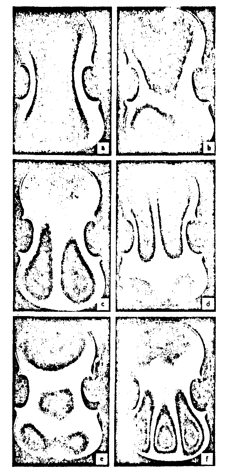
fig.8. time-average hologram interferograms the top plate of a violin under construction, without f holes and bass bar. the frequencies are: a 550 hz, b 800 hz, c 810 hz, d 100 hz, e 1110 hz, f 1220 hz.
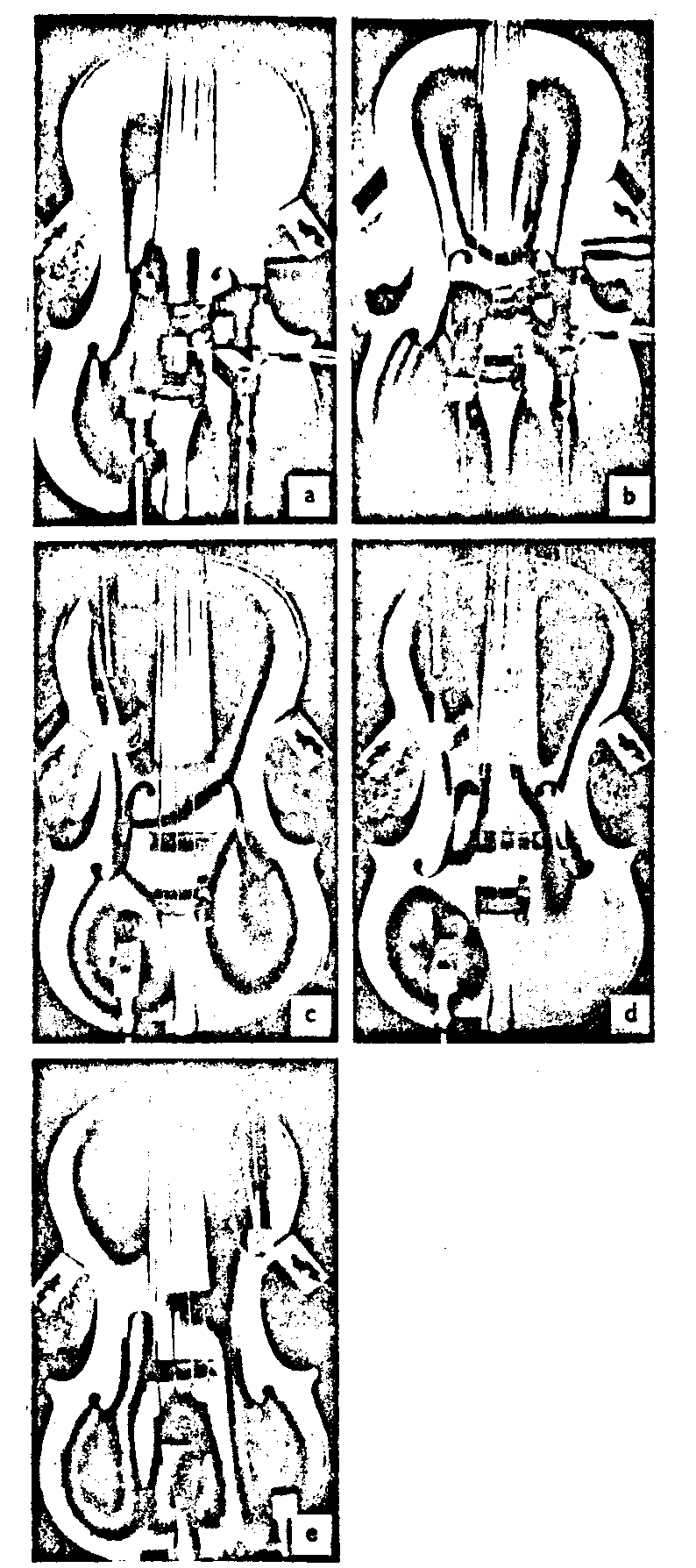
fig.9. interferograms of the top plate in the complete instrument. a 480 hz, b 780 hz, c 830 hz, d 950 hz, e 1100 hz.
rometry comes in as natural. with this technique, the granule pattern can be observed directly in real time.
work on this line is in progress but temporarily upheld awaiting the installment of a strong ar laser which will improve the possibilities of measuring, not only observing, the vibration amplitudes.
thick holograms produced by means of stabilized
photographic films
recording materials
holograms recorded in light sensitive layers whose thickness is large relative to the period of the interference structure, require fulfillment of the bragg condition for the reconstruction process. accordingly, thick holograms are more or less selective with respect to the angle of incidence and the wavelength of the reconstructing field. because of these properties thick holograms are of great interest for many applications where ordinary thin holograms are insufficient. among these can be mentioned multiple Image recording in a single hologram by means of superpositin, permitting separate reconstruction of each Image, preparation of true color holograms or monochrome holograms which can be reconstructed by white light. furthermore thick phase holograms may have a diffraction efficiency approaching 100 %.
recording materials for preparation of volume holograms are, in the first place, photochromic materials together with alkali halide single crystals and ferroelectric crystals, and photopolymer materials. for the three firstmentioned groups, thicknesses from 0.1 to 10 mm, typically 2 mm, are reported, while photopolymer layers range from 10 m to 1 mm.
photochromic glass only forms absorption holograms which inherently hava very low diffraction efficiency and therefore in many cases are of less interest. the crystals which forms phase
holograms have a size of a few square centimeters, at the most, and hence restricted applicability. the photopolymer materials may form phase holograms of sufficiently large size. the major drawback of all the materials listed, however, is their low sensitivity: the exposure required for forming a hologram is of the order of magnitude of ws/cm2 for the photochromic materials and the crystals and mws/cm2 for photopolymers. even the exposure for photopolymers may, apart from laser power requirements, be prohibitively high with regard to the biological radiation damage threshold, e.g. for holographic portraits. furthermore all these materials are sensitive only to uv and the shorter visible wavelengths.
photographic silver halide emulsions designed for holography, on the other hand, require an exposure of about 1 to 10 ws/cm2 only. they can be sensitized for desired wavelengths, a property, which qualifies them for hologram recording in colour and also with pulse lasers. the formation of a latent Image prevents, in the case of multiple recordings, the interaction between the already recorded holograms and the incident field.
the talk here gives a short summary of the paper /8/ to which the reader is referred for full information. work is also in current progress.
holograms in swollen gelatine emulsions
photographic plates immersed for exposure, processing, and evaluation in the liquid gate of a hologram interferometer, see /5/, assumed an about 8 times increased emulsion thickness in the aqueous solutions and exhibited all the properties of volume holograms. they were also found very suitable for lippmann -denisyuk-type reflection holograms with white-light reconstruction. hence, it appeared, that swelling the emulsion by means of a suitable liquid and then stabilizing this thickness would be a method that combines the advantages of silver halide emulsions as a hologram recording medium with the properties of volume holograms.
stabilization of thick holograms
in exploratory experiments with commercially available water soluble urea formaldehyde reaino, it was found that only with very diluted solutions did the gelatine layer remain swollen, in this way, too little substance was imbedded as to harden properly and to keep the layer at a sufficiently extended thickness. therefore, special combinations of solvents, polymere, and hardeners had to be sought.
generally, swelling is promoted by polar solvents, and the largest swelling is obtained from strongly acid or alkaline solutions in absence of salts. for the chemical processes involved, many conditions must be fulfilled: the compounds must not react with the silver or silverhalide or the emulsion, be able to diffuse into the gelatine, be watersoluble and the polymerizing reaction must proceed at low temperature (less than 60-70°c). organic polar solvents like glycerol and ethylene glycol were found to produce the desirable swelling of the gelatine by four to ten times. fairly good results were obtained with a procedure involving derivatives of poly vinyl-alcohol solved in glycerol. applying these substances to holographic plates agfa-gevaert scientia 8e70 an initial swelling by a factor of about eleven, i.e. a thickness of around 70 m was obtained. during the complex forming process, which is rather slow at room temperature, some loss of solvent could not be prevented. after three months, the thickness had more or less asymptotically decreased to a value of around 30 m, which, however, still represents a thickness extension of four to five times.
the thickness values were obtained indirectly by measuring the function of primary interest, namely the dependence of diffraction efficiency on the angular deviation between reconstruction and reference beam. an experimental curve la showr as a dashed line in fig.10.
whereas the experimenta proved the feasibility of stabilizing the extended thickness of swollen photographic gelatine la-
yers, appreciable development work for faster and more uniform hardening would be prerequisite for practical applicability.
even the more straight-forward method of preserving the thickness by sealing the liquid gate or by coating the hologram with a suitable substance in order to prevent the swelling liquid from evaporation, has been investigated. from 15 m thick agfa-gevaert scientia 8e75b plates, good holograms with a thickness of 110 m have been prepared by swelling the layer in glycerol and coating it with a liquid polyester of the kind that is on sale for moulding paperweights and the like. the bolid curve of fig.10 shows the bragg-angle dependence of the diffraction efficiency. in photochromic glass, 100 holograms of
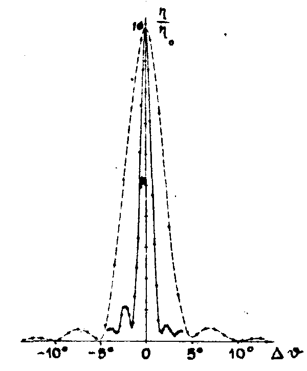
fig.10. relative diffraction efficiency versus angular deviation of the reconstructed beam from bragg-angle incidence.two-beam interference exposure: object beam normal to the plate, reference bean at 20° to normal. dashed curve refers to hologram stabilized by hardening substance within the emulsion. thickness estimated from the angle between the first zeroes in the chrve is 35 m. solid curve refers to hologram stabilized by overcoating with polyester. sorae geometry, but with two object beasis 1° apart, of which the reconstruction of the inner object bean is plotted. estimated thickness 110 m. both curves measured 3 months after stabilization treatment.
transparencies have been stored as reported by friesem and walker. in analogy, our group superimposed 30 holograms of a diffusely reflecting object in one photographic plate. sour of the reconstructed images are shown in fig.11.
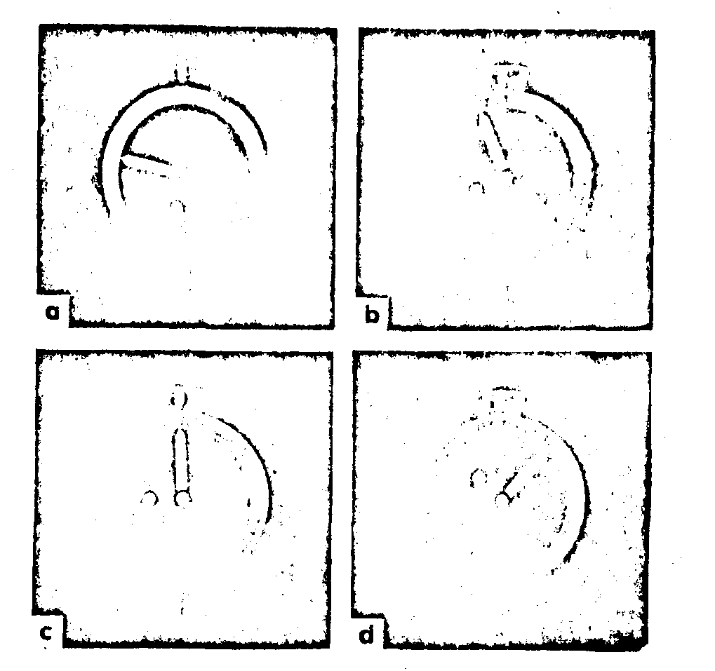
fig.11. reconstructions from a multiple exposure hologram containing 30 sequential recordings of a 3-dimensional object. agfa-gevaert scientia 8e75b plate, dry thickness 15 m, swollen in water to about 100 m. thickness stabilized in glycerol; coated by glass plate and sealed around the edges with polyester. geometry: at the first exposure, object at normal to the plate, reference beam 60° to the normal. plate turned by 2° between subsequent exposures. figs.(a) to (d) show reconstructions of recordings 1, 11, 15, and 24. bright glare in fig. (a) is due to unidirectional machining of the object surface.
for both methods, the swelling liquids have to fulfill at least two conditions imposed by the bragg-relation: 1) they have to adjust the photographic layer to identical thickness both at the recording and the reconstruction of the hologram; 2) the average index of refraction within the extended layer has to have the same value at both occasions. in ordinary silver halide volume holograms, unless phase holograms by reversal development are made, removal of the silver halide by the fixing bath lowers the bulk refractive index of the layer by about 0.1, a change that cannot be fully compensated for by changing the thickness. this problem can be overcome in our experiment by using water (n = 1.33) at exposure and e.g. glycerol (n = 1.47) at reconstruction, making an increase in the average index of refraction of up to 0.12 possible. the measuremsnts show that the swelling promoted by a glycerol-water solution is virtually constant and approximately the same as for pure water for all concentrations between around 25 % and 100 % glycerol, hence it should be possible to tune the refractive index continuously while keeping the swelling constant.
used the other way, adjustment of the index of refraction could, to the first approximation, allow aberration-free reconstruction of either thick transmission or reflection type holograms with a wave-length of the order of 10 % shorter than that of the recording. a volume hologram recorded with a ruby laser (
= 578 nm).
the use of speckle interferometry for measuring
vibrations in real-time, including electronic
treatment of the speckle pattern
the concepts of speckles date very far baok. but first when the highly coherent laser light came, the properties of the
spackles were more closely studied. a short description of the phenomena is the following:
when a rough surface is illuminated with laser light, the scattered light forms a three dimensional speckle pattern in the space around. the size of those speckles is depending on the distance from the illuminated surface and its area. the same is true for a diffusing material which ia transilluminated. this speckle pattern arises from interference between the many individual wavelets coming from different points of the illuminated surface, each with random phase with respect to its neighbours.
if an Image device, such as a human eye, a camera etc., is forming an Image of the illuminated object, the Image will exhibite a speckled structure, where the phase and amplitude in the Image is determined by the resolution of the used device.
now, if some parts of the object surface are moving, the phase and amplitude in the speckled Image of these parts will change simultaneously. thus the individual speckles will neither be constant in position nor intensity due to the changing phase-relations from the moving surface.
if the imaging device has an integration time which is long enough, those areas will be more or less blurred depending on the amplitude of the vibration object surface and the transforming aperture of the Image device.
the different methods in use (there are several hundred publications) have the advantage of real time observation, either using the human eye directly or a tv-camera with minotor.
there are however several practical difficulties with real time observations. as far as visual observation is concerned, different persons have different ability to see the contrast between a blurred and an unchanged (static) speckle pattern.
in the case a tv-camera is used, one of the advantages is, that it is possible to process the Image electronically and thus increase the contrast. the video signal from Image areas with static speckles has modulation mear one, while in areas
with moving speckles the time integration of the vidicon reduces the signal modulation. into the system a discriminator is inserted which amplifiers signals having a modulation above a critical value. a picture with vibration pattern enhanced is displayed on the monitor.
since the vidicon has a limited resolution only small apertures can be used: with a given laser power only a limited area can be tested.
in the case the feet area is illuminated with a spherical field the test area can be increased by covering it with retro reflexive paint and use a slightly modified set up.
it is possible to increase the area under test using more sensitive vidicons, such as bbs and sec vidicons. for example, with a westing-house ebs vidicon an area larger than 1/2 m2 could be studied when illuminated by a 5 mw he-ne-laser.
work is in progress, and some of the procedures are protected by a patent /9/.
calculation on speckle geometry for the use of speckles
for eye refraction measurements
a b s t r a c t
after a brief outline of the formation and properties of laser produced speckles, the talk describes a method of measuring the eye refraction based on the observation that the speckles from an illuminated surface appear to move when the surface and the eye have an angular movement relative to one another.
formation and properties of the speckle patterns
in tills abridged version of the full papers written, we only give some short notes on the principle and the construction of an apparatus for eye refraction measurements. paper /10/ is practically the same as the printed one /11/, but contains some
more details of calculation.
the theory of the formation of speckles, and the general properties of the speckle patterns are totally left out here as known and also accessible in our papers.
perhaps the most conspicuous property of the speckles is the fact that the pattern in general is not stationary with respect to the surface when the surface or the observer moves perpendicularly to the line of sight, but rather moves in the same direction or in the reverse direction. in order to observe any speckle motion at all, it is however, necessary that the speckles are not too large (which means that the observing aperture must not be too small), because during the movement all individual speokles slowly change due to the changes in relative phase differences between the surface points, and after a certain distance the identity of the pattern is completely lost. the average distance which the speckle patterns may translate before their identity is lost is called the correlation distance and must be larger than the average speckle size if any motion shall be observed. otherwise the speckle pattern will change continuously with time and appear like "boiling".
speckles used for examination of the refraction
state of the eye
the property of the speckles to appear to move with respect to the surface as the observer moves his head or the surface is moved in a direction perpendicular to the line of sight, is explained from the fact that the speckles are just interferences created on the observer's retina. a couple of year ago, however, it was discovered that this apparent motion of the speckles could be in the same direction as the movement of the observer or the opposite and that this direction was systematically related to the state of the eye, namely its normal correction and its actual accomodation relative to the surface. assuming a normal
eye, movement of the speckles in the same direction as the observer's eye, or, in the case the surface moves and the observer in stationary, movement in a direction opposite to that of the surface, indicates underaccomodation. if they move in the opposite direction this implies too much accomodation. if the speckles do not move, just seen to "boil", the observed surface is supposed to be optically conjugate to the retina. these phenomena have been observed and studied by many workers.
as mentioned, these phenomena seem to have a certain use as a method for examining eye refraction. since it is for this purpose equivalent whether the observer moves or the surface moves, it is more convenient to let the surface move and keep the eye still. thus a slowly rotating cylindrical surface was found to be suitable. fig.12 is given as an example of a surface we have used.
the arrangement is used in the same way as an ordinary eye examination, with lenses from a trial set placed in a frame and varying them in steps of 0.25 diopters. however, instead of judging which glass is optimal for reading the letters in an eye chart, the observer decides whether the speckles move to the right, to the left or stand still (boiling). since this method seems to be very sensitive to changes in the state of accommodation, it is very important that this can be kept fixed. either the eye should be relaxed (focused at infinite distance), or have a defined accommodation. for the latter case we have, in our apparatus, introduced some marks on the drum, on which the observer can focus his eyes while observing the speckles.
the main aim of this investigation has been to examine the basic optical questions which arise as regards the formulation and motion of these speckle patterns in different geometries of the moving surface. here three different configurations have been studied: (1) a rotating plane wheel, (2) a plane translating surface (belt); and (3) a rotating cylindrical surface (drum). for the detailed results, see paper /11/.
in the tests we have made, the cylinder la placed at a distance from this observer that is large enough to approximate in-
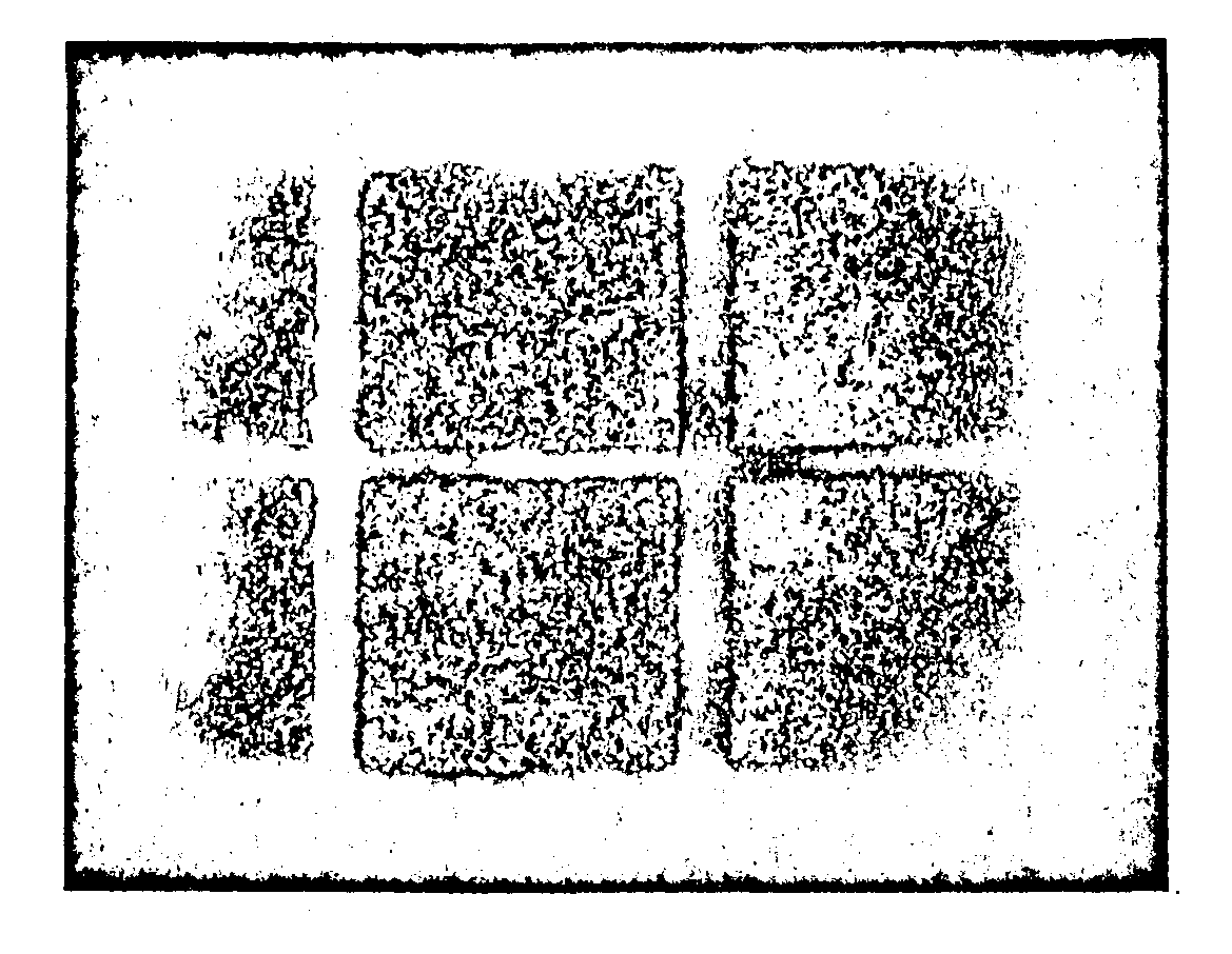
fig.12. speckle pattern produced by laser illumination of a cylindrical surface such as used in our experiments.
finity without introducing too much error.
the power d, in diopters, of the correcting lens needed for the relaxed eye to bring the speckle pattern to a standstill in calculated to be

where
fig.14. table showing the results of measurements on 12 members of the staff of the institute.
as a conclusion can be said that this method of measuring the eye refraction has definite advantages over the conventional methods in that it is very sensitive) and in that it is more objective. it is more objective in the sense that the testing criterion is binary: either the speckles move or they do not, compared to the problem of deciding whether the letters on a test chart are more or less legible. it is, however, not objective in the sense that the results can be controlled by another person. it may also be an advantage that the measurements can be made either with the eyes focussed on the drum or with the eyes completely relaxed (if the drum rotates slowly enough). the first case, however, has the disadvantage that it is difficult for some people, in order to keep the state of accommodation constant, to focus onto the drum and at the same time observe the speckle motion. in the case of the relaxed eye, it may on the other hand be difficult to keep the eye unaccommodated.
probably the moot important advantages are that the method can be used to test children and illiterates who cannot read the letters on a test chart, further, the method might be used to simultaneously test a large number of persons. the test is simples those who see the speckles move might need correction glasses, the other not. it may, however, in many cases be difficult to explain to the observer what he is expected to see.
the speaker wants to thank all the collaborators of the institute for their work in abstracting what can be considered as relevant for this communication, and mrs. christina nordin for typing and editing it.
the excerpts of earlier publications are made with the consent of the copyright holders.
r e f e r e n c e s
comm (communications) arid tr (technical reports) relate to the series of publications issued by the institute.
1. s.walles. visibility and localization of fringes in holographic interferometry of diffusely reflecting surfaces. comm.156; arkiv fysik, 40, 299, 1970.
2. s.walles. on the concept of homologous rays in holographic interferometry of diffusely reflecting surfaces. comm.166; optica acta, 17, 899, 1970.
3. n.e.molin, k.a.stetson, measurement of fringe loci and localization in hologram interferometry for pivot motion, in-plane rotation and in-plane translation. comm.155; optik, 31, 1970.
4. n.e.molin, k.a.stetson. fringe localization in hologram interferometry of mutually independent and dependent rotations around orthogonal, lion-intersecting axes, comm.168; optik, 33, 399-422, 1971.
5. k.biedermann, n.e.molin. combining hypersensitization and rapid in-situ processing for time-average observation in real-time hologram interierometry. comm.157; j.phys. et sci.instrum., 3, 669, 1970.
6. k.a.stetson, c.h.agren. measuring the resonances of treble viol plates by hologram interferometry and designing an improved instrument. comm.150; j.acoust. soc.amer, 1971-1983, 1969.
7. e.jansson, n.e.molin, h.sundin. resonances of a violin body studied by hologram interferometry and acoustical methods. comm.170; physica scripta, 2, 243-256, 1970.
8. k.biedermann, s.i.ragnarsson, p.komlos. volume holograms in photographic emulsions of extended thickness. comm. 176, optics communications, vol.6, no 2, 205-209, 1972.
9. l.hode, k.biedermann. observations of surface deformation in real time using laser speckles. tr 1972-03-30;
abstract swed.phys.conf., lund, 1972.
10. s.i.ragnarsson. calculation on a method for eye refraction measurements using laser-produced speckle patterns. tr 1971-07-19, 1971.
11. e.ingelstam, s.i.ragnarason. eye refraction examined by aid of speckle pattern produced by coherent light. comm.172; vision research, 12, 411- 420, 1972.

