a holographic camera for variable proceedings
h.lenk, f.hodam, h.sanders
zentralinstitut für optik und spektroskopie, ddr
i n t r o d u c t i o n
holograptly itself is not only object of intensive research work, but it become more and more a tool for scientific research in other fields. besides of that, application, especially for measuring and testing processes, is of interesting importance. it was tried to take into account this trend by production of special laboratory units, by development of series of units and by production of laboratory equipment for holographic research /1-3/. in some cases these devices are adapted to a special purpose of application, for example /4,5/ in other cases they are relative many-sided but they have the character of laboratory arrangement and a lot of work must be done for changing the procedure.
object in view
with our development of a holographic camera we aimed at the creation of a laboratory type of a device, in which a certain comfort of working is connected with versatility in relation to the choice of the methods and the possibility of applications. in this way it should be possible that persons, for whom holography is only an auxiliary tool, can do holographic experiments, without having trouble with a lot of experimental work.
it was aspired to develop an equipment by means of which fresnel-holography in incident and transmitted light, the corresponding reconstructions and in-line-holography are possible. as the holographic 1:1 imaging seems to be most important, we work with a plane reference wave. vor adaptation to several registration materials resp. conditions of resolution a choice between two carrier - frequences is possible. additional units for the photographic shoot of the virtual or the real Image are in use, especially there exists
a device for the observation and the photogrammetric evaluation of the virtual Image. by using the technique of double-exposure resp. by use of a special plate-holder the equipment is suitable for holograminterferometric investigations in "frosen fringe" or "live fringe" technique.
basic arrangement
the whole camera system is carried by a stable watered ground-plate which rests on three solid concrete foundations. these are damped against vibrations by means of sponge rubber. it turned out that in this way action of vibrations in the building could be eliminated. fig.1 demonstrates the external view of the equipment.
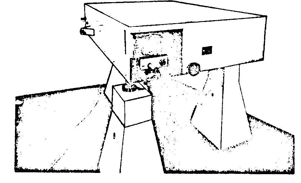
fig.1. holocamera, outside view.
the camera is closed lighttight; by means of the flaps (3) the most important constructional units and the objects space are accessible. the handwheel (1) serves for the turning movement of a collimator. for realizing the carrier-frequency proceedings with oblique reference wave, the basic optical setup corresponds to a triangle with variable sides and angles.
an optical solution was aspired which offers the following possibilities:
a) to use as few constructional units as possible, that means to use one and the same element in several ways;
b) to switch from one method to another by means of simple mechanical movement of elements resp. groups of elements;
c) to work in the carrier-frequency proceedings with aligned means path difference between object and reference path. this can be done for instance in the following way.
model of the proceedings
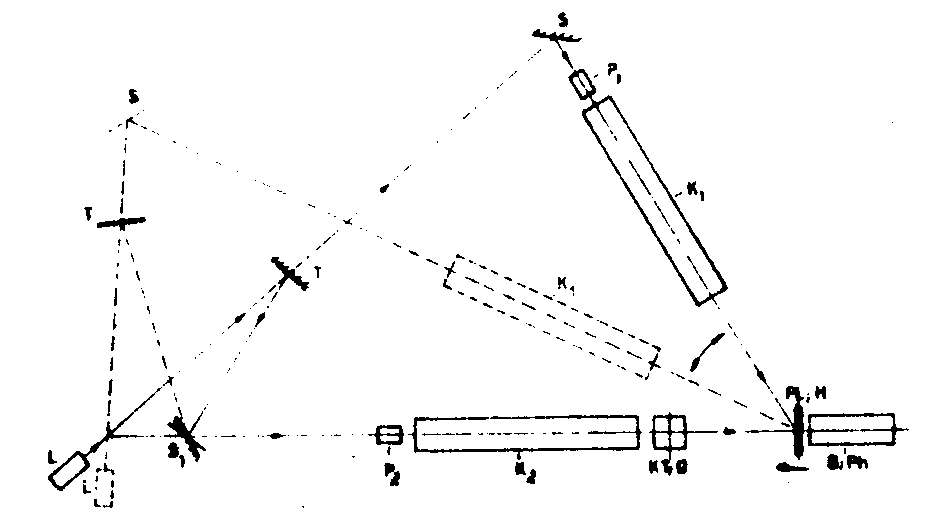
fig.2. model, transmitted light, carrier-frequency.
fig.2 demonstrates the optical setup for the holographic taking of objects with carrier-frequency in transmitted light. the light boundle comes from the laser l and incides with different angles into camera, corresponding to the elected carrier-frequency. (in reality the light source will not be swinged, but the laser can be fitted at the left side of the camera and the different directions of incidence are obtained by means of mirrors. the beam is divided at the half silvered mirror t, the reference path follow the way via mirror s and collimator k1 to the holographic plate pl; h and the object path follows the way from t via a mirror s1 being placed in the prolongation of the optical axis of collimator k2, through the collimator k2 and the object o to the holographic plate. for
the alignment of the second carrier-frequency the direction of incidence of the light beam is changed, so that it strikes two other mirrors t and s, the collimator is turned to the new position and mirror s1, is also turned.
in the following part the mirrors t and s belonging to the lower frequency will be denoted by ta, sa and those belonging to the high frequency with tb, sb. in fig.2 further denote: p1, p2 polarizing or other elements for the attenuation of the light intensities, kt measuring table at the space of the object and b; p is a device for the observation or photographing, to evaluatethe images reconstructed from the hologram.
in fig.3 the optical setup for the holographic taking of objects in incident light with carrier-frequency is demonstrated.
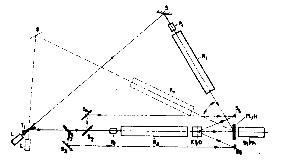
fig.3. model, incident light, carrier-frequency.
the incidence of the light into the camera is the same as in fig.2, also the angles of incidence are the same. now a beam-deviding mirror t1 is situated in the prolongation of the optical axis of collimator k2 and causes the division into reference and object beam. the reference boundle is guided in the same way as before, the beam dividers t are turned out of the ray path. for the illumination of the object, the light is divided once more as the half-mirror t2, the light is then guided besisde the collimator via s2, s4 resp.s3.
it strikes two spherical mirrors which are situated in the elongated diagonal of the holographic plate for illumination of the object. for the transition to the other frequency again k1 is turned and also t1. all other designations hare the same meaning as in fig.2.
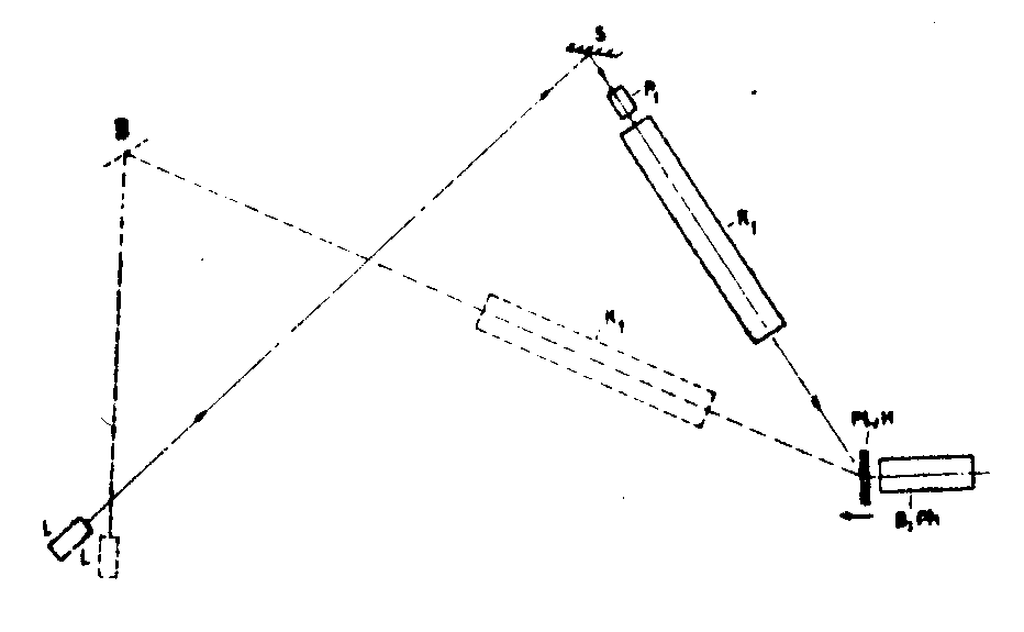
fig.4. model, reconstruction, carrier-frequency.
as is demonstrated in fig.4, the transition to the reconstruction, starting either from fig.2 (transmitted light) or fig.3 (incident light), is possible by simple removal of the beam-dividers t resp. t1 out of the ray path. the small lateral displacement of the boundle which appears, can be eliminated by a fine parallel displacement of the mirrors which guide the light into path.
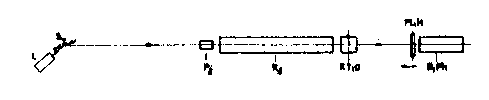
fig.5. model in-line proceeding.
in fig.5 the optical setup for in-line holography is deinonetrated. by means of a mirror s7, situated in the extension of the optical axis of k2, the beam is guided into the collimator. reconst-
ruction is done in the same way.
in principle it is possible to switch over from every proceeding to every other directly. nevertheless it is advantageous to proceed during the transition according to the model of fig.6, because in
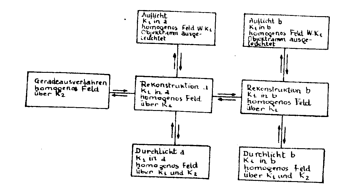
fig. 6. model, transition of proceedings.
that case apart from index marks for the certain positions of the mirrors also optical criterions, for example homogenlty of the illuminated field, can be used for the fine adjustment of the setup. in the bordered positions of fig.6 the just selected proceeding is specified together with its criterion of adjustment. the arrows are marking the direction of the transition. next to it the necessary manipulations are declared. with the letter b the high frequency (about 1300
l/mm for λ=632.8 nm) is designed and with a the lower frequency (about 670 l/mm). ssv means a glide conveyer which carries a group of five mirrors (t1, t2, s1, s2, s7) in appointed positions. us1 and us2 are the denotations of the mirrors for guiding the beam into camera. they are not plotted in figs.2-5. z designes a pull rod for turning of the dividing mirrors t.
important structural components of the camera
mirror ensemble.
as the transition from one proceeding to the other was solved purely mechanically, it was necessary to look for an arrangement which requires only few changes of positions. it turned out to be of advantage to mount some mirrors (sa, sb, s3, s4) in fixed positions. the beam dividers ta , tb can be turned out of their position simultaneously. other mirrors (t1, t2, s1, s2, s7) are mounted on a common support slide which can be moved in defined positions in a derection forming an angle of 45° with the extended optical axis of collimator k2. the spherical mirrors s5, s6 can be turned slightly for optical illumination of the object. the mirrors s1 and t1 can be turned also. with the assistance of the operating instructions it is easy to handle the necessary manipulations.
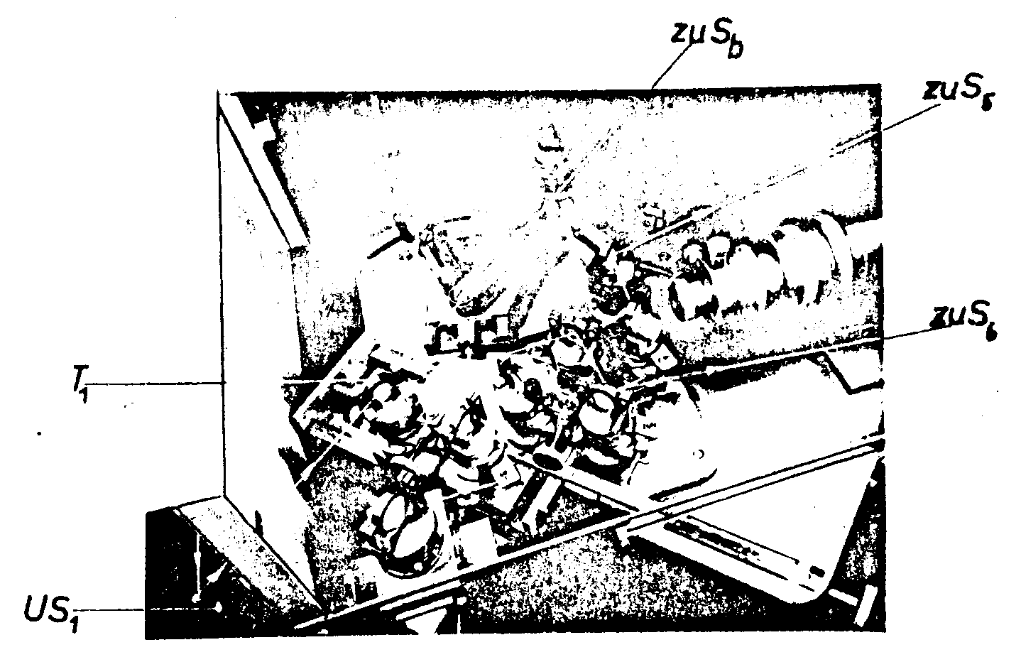
fig.7. mirror-ensemble, incident light, nigh frequency.
fig.7 demonstrates the mirror-ensemble in the operation-incident light, high carrier-frequency. the reference path is guided via t1 to sb and the object illumination to s5 resp. s6.
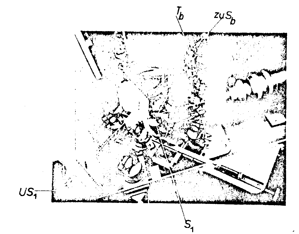
fig.6. mirror-ensemble, transmitted light, high frequency.
in fig.8 the operation-transmitted light, high frequency are demonstrated. beam division occurs at tb, the object beam is guided via s1 to the illuminating collimator.
collimators.
k1 and k2 are two identical collimator arrangments consisting of a focusing micro-objective, pinhole and an astronomical objective (aperture 110 mm, focal length 750 mm). if objectives of smaller focal length are used, the size of the camera can be reduced.
plate-holder mounting.
fig.9 demonstrates the mounting for the plate-holder
in which the holographic plate (size 9 x 12 cm) is inserted. front side and reverse of the plate-holder can be closed lighttight. in the figure one can see the operating elements and
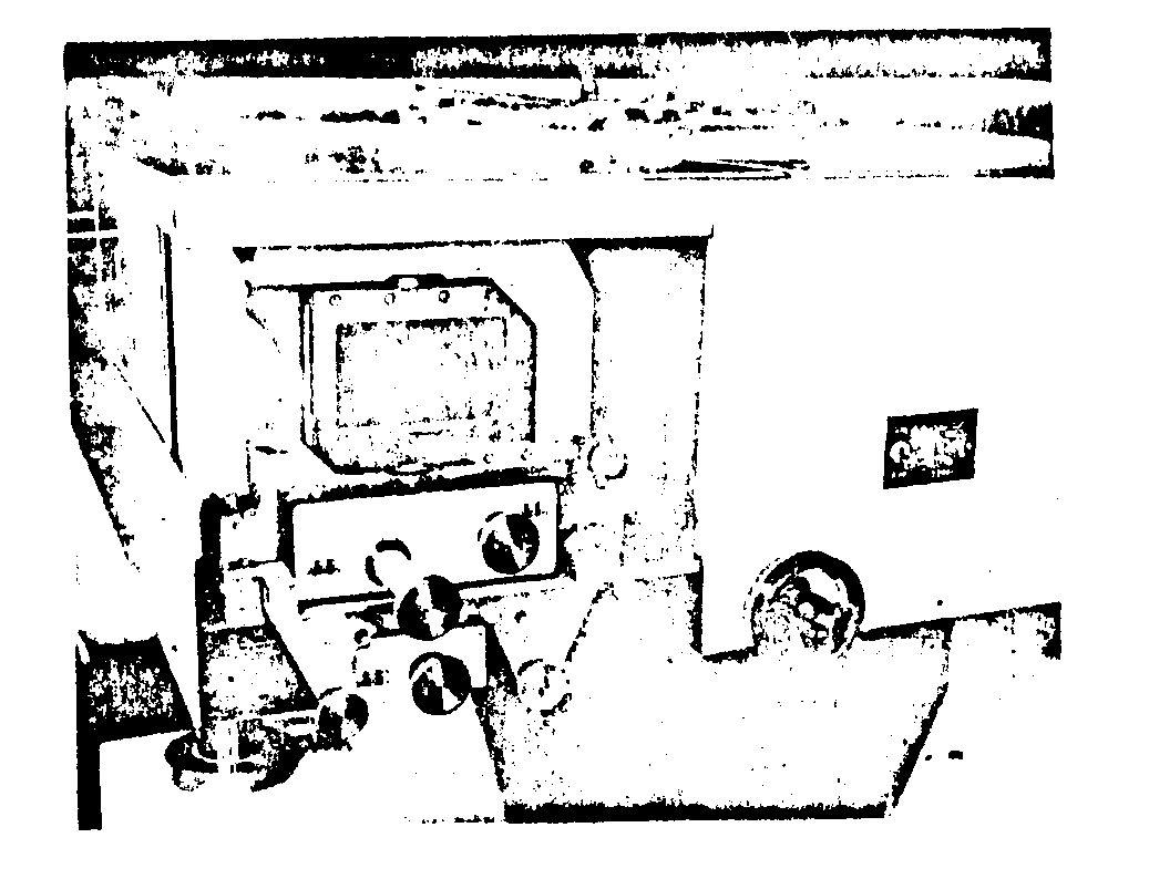
fig.9. plate-holder mounting.
the reading apparatus which serves for translation of the measuring table for the photograinmetrio evaluation of the virtual Image.
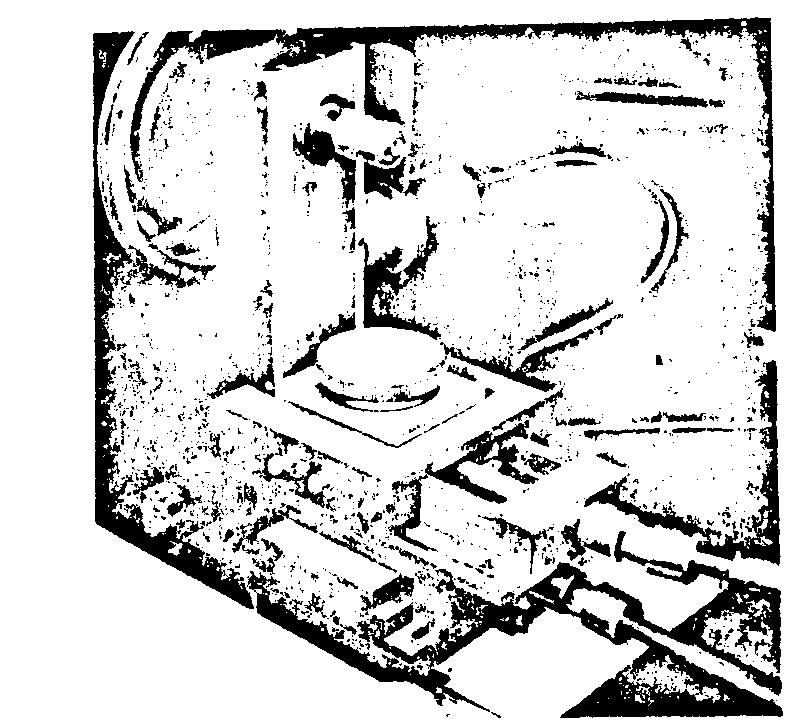
fig. 10. measuring-mark projector.
measuring table.
the measuring table can be translated in three perpendicular directions with an accuracy of 0.01 nun (fig.10). during talcing the hologram it serves for fitting the object. for the purpose of measurement it carries a measuring mark projector which forms the Image of an illuminated mark at the position of the Image. it is possible to measure objects of the maximal size of 50*50*50 mm with the table. corresponding to the cross section of the light boundle,objects of about 100 mm diameter can be taken bolographically.
observation equipment.
the equipment for the observation of the virtual Image during the measuring process is demonstrated in fig.11.
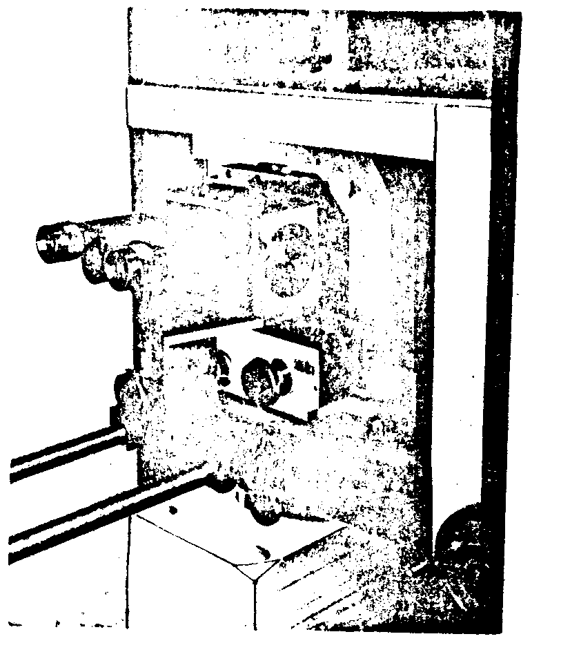
fig.11. observation unit.
the question is of a telescopic magnifier (over-all magnification 4,3). it consists of two usual prismatic telescopes with adjustable
eyepieces and variable eye-distances. in the housing the magnifying lens is mounted. it can be translated in axial direction by means of a focusing screw. in this way focusing on different depth positions in the Image is possible. the mean working distance at middle position of the focusing screw is a distance of 300 mm between hologram and Image. for observation of Image parts outside of the optical axis the whole telescope can be turned. lateral of the equipment are three operating screws for the translation of the measuring table in three perpendicular coordinates. after fitting of object details in the virtual Image the operator can read the positions of the screws.
photographic equipment.
the just explained equipment for observation can be exchanged with a photographic device for the photographic shoot of the virtual or the real Image (fig.12).
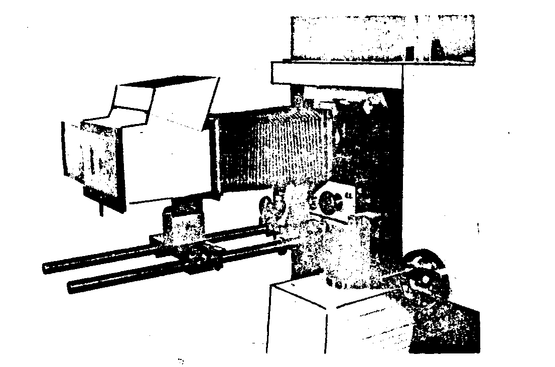
fig.12. photographic unit.
it is a usual camera for microphotography with an objective tessar 4.5/210 mm. with the objective inserted, one can take the virtual Image, with the objective removed, the real Image. the Image can be observed on an attachment with a ground-glass. by means of translation of the objective-carrier and the film-holder, changing of the magnification is possible. focusing is done with a fine-adjusting
screw.
the next figures demonstrate the complete camera equipment. fig.13 demonstrates an alignment for low frequency and fig.14 - an alignment for high frequency. the corresponding structural components can be seen clearly.
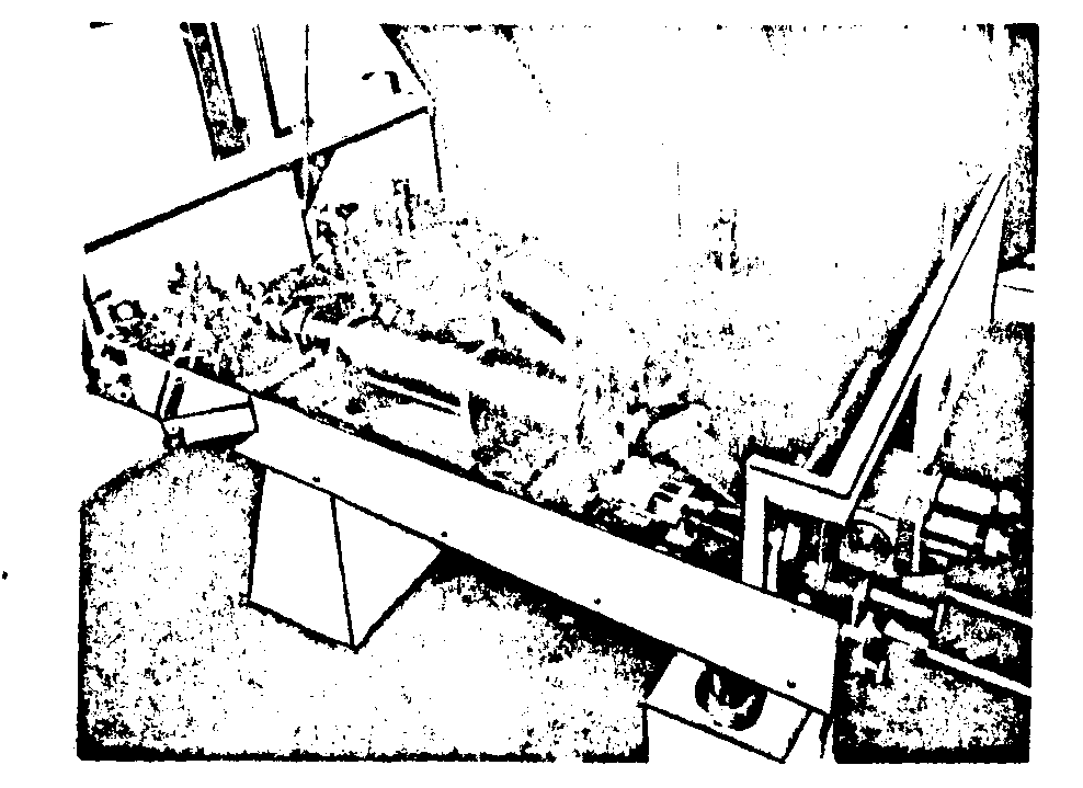
fig.13. camera equipment (low frequency).
fig.14. camera equipment (nigh frequency).
application of the camera.
corresponding to the many-sided arrangement the possibilities for application are rather broad. in the in-line setup basic holographic experiments for teaching and demonstration can be done. by inserting of corresponding cuvettetes into the object space and the use of impulse illumination holographic photos of three-dimensional particle distributions in liquid or gaseous media can be taken. the proceeding in transmitted light with carrier-frequency makes possible the performing of basic experiments, the holographic shoot of static distributions reap. of dynamical distributions with impulse illumination in transmitted light. holograhy of phase objects for later examination, simple investigations in polarization optics and tests of homogenity also are possible.
in incident light besides of basic experiments the following procedures are possible and of interests the spatial holographic shoot of static or fluctuating objects and the documentation of three-dimensional objects or models connected with a photogransinetrio evaluation of the Image.
by use of the double-exposure technique and utilisation of a special plate-holder mounting the field of application can be enlarged, toward testing of shape and state by holographic interferometry. if one uses adjacent laser frequencies surface-contouring is possible.
fig.15. reconstruction (transmitted light).
fig. 15 demonstrates the reconstruction of a simple object in transmitted light which was taken without special technique and fig.16 demonstrates the reconstructed Image of an object taken in incident light. this object was at the same time one of the test-objects for photogrammetrio measurements.
fig.16. reconstruction (incident light).
some bemarks to photographic svaluation.
photogrammetry at short object distances is a special and difficult field of photogamnrtry. it deals with objects which cannot be measured directly or with time-variable events which can't be analysed before registration. holography offers the possibility to simplify the procedure, there exists no problem with depth of focus and no carefully oalibrated camera with variable focal length is necessary.
a problem is till now, that visual fitting of the holographic Image is required. with this the uncertainity of measurement in fitting of one Image point plays an important role. we carried out some investigations to this problem, which yielded similar results as works of other authors which were published in the meantime /4-7/.
the accuracy of measurement is smallest in axial directie on (z-coordinate), while the accuracy for the other coordinates is nearly one order of magnitude better. in /7/ for example for the mean error in the x,y and z-coordinate values of 0.03; 0.03 and 0.1
mm are given, if auxiliary optical tools for the observation are used. without auxiliary tools the uncertainty of the measurement is 0.2 - 0.3 mm /4-7/.
our measurements which we carried out as a first step in making the camera, for an object distance of 300 mm and an eye-base of 65 mm also yielded a mean error of 0.2 - 0.3 mm. a simple evaluation demonstrates that these values have to be expected and in which way an improvement can be obtained.
in a measuring triangle (fig.17) which is constructed of the base-line b and the connecting line from the pupils to the fitted objectpoint,
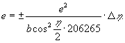
η designates the angle of convergence and e - the distance between object point and base-line.
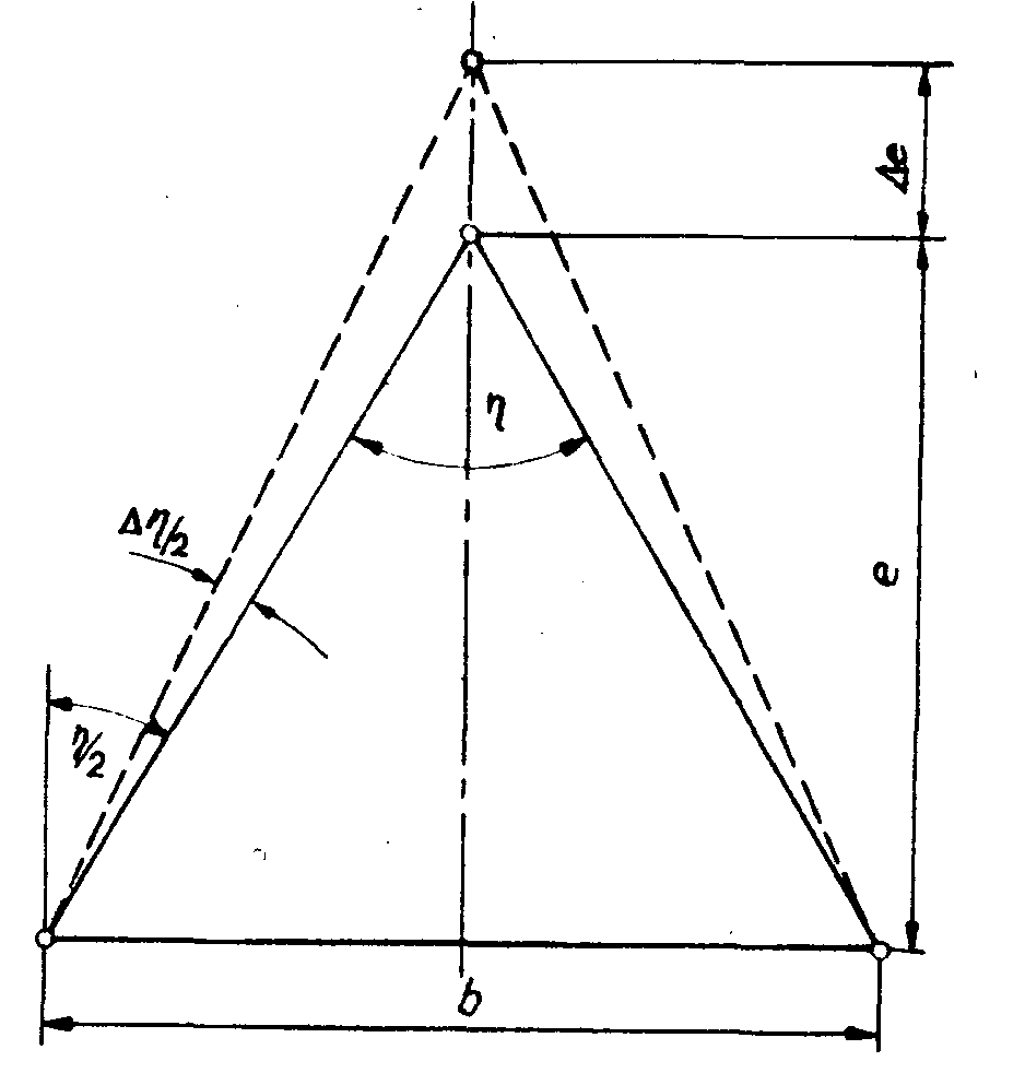
fig.17. photogrammetric measurement.
it is valid
 , where e
=
f (b, η). (1)
from eq.(1) yields
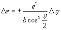
with this the error propagation law for the expected uncertainty can be written
 (2)
(2)
as Δb=0 yields from eq.(2)
 (3)
(3)
by expressing eq.(3) in second of angle we obtain
 (3a)
(3a)
as for the appearing angles of convergence the approximation
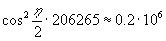 holds, from eq.(3a) yields
 (4)
(4)
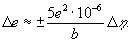
if we insert for  instead
of the from the keenness of vision resulting value of
instead
of the from the keenness of vision resulting value of
Δη≈10''
a value of Δη≈20'' which certainly is more true for routine
measurement, we obtain from eq.(4).
 mm for e=300
mm.
mm for e=300
mm.
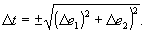
if two points are situated in the distance e1 and e2 from the base and we denote with t=e2 - e1 their distance in z-direction, we obtain for the uncertainty of measurement
 (5)
(5)
with a mean object distance of 325
mm and Δη≈20'' results a mean error in the depth measurement of Δt= ±0.23 mm.
by using on optical system with magnigication
Г for the observation of the Image eq.(4) has the form
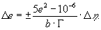 (4a)
(4a)
here can be learned, that an improvement of measuring accuracy is possible in the following way:
enlargement of the eye-base;
deoreazing of the object distance;
usage of a magnifying system.
several limits exists for these possibilitites, for example range of distinct sight, extension of the field of vision, size of the hologram. in our case we worked with a magnification of
Г=4.3. from these results a Δt < 0.1 mm for measurements in z-direction.
from measurements, which we carried out,can be expected, that the mean error for the measurement of depth in the Image of the object will be not greater than ± 0.05 mm.
references
1. j.c.buges. compt.rend., 268 b, 1624, 1969.
2. d.h.close. appl.opt., 11, 376, 1972.
3. b.a.antonow u.a. opt.laser technol., 4, 220, 1972.
4. pavligin. iii school for holography, uljanowsk, 1971.
5. e.mikhail. u.a. symp.photogramm., urbana, 1971.
6. u.k.hurts. thesis, purduc-univ, 1971.
7.o.o'connor. laser, 2/1972, p.33.


