information processing in conventional andreal-time holography
valentin i.vlad institute of atomic physics, bucharest, romania
i n t r o d u c t i o n
the aim of this paper is to show some aspects of information processing in holography related mainly to obtaining real - time holograms (rth). we shall analyse the compression of the message bandwidth in the holographic registration using an analogy with the pulse compression in "chirp" radar. a study of the principal parameters of the holographic support shows that a further spatial bandwidth reduction leads to a decrease of signal to noise ratio (snr) or space bandwidth product (sbp).
keeping in mind these considerations we present some methods of hologram bandwidth reduction useful for rtb transmission via tv channels and simultaneously for a complex processing of optical information.
finally, we present some materials used in our experimentd for obtaining rth.
compression of the message bandwidth in the holographic process
in a previous paper /1/ we have shown that the useful term of the nonlinear holographic registration can be obtained by a transformation of the object wavefront in a cascaded lens-prism system (lpm, fig.1). in the fourier space the transformation of the object wavefront into the useful interference tern (one side-band) is obtained with a bandpass propagator (tilted plane processor, figs.2 and 3a). the reconstruction process corres-
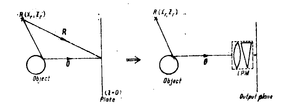
fig.1. equivalent lpm for the one side-band holographic transfer of information.
ponds to an inverse transfonnation (lpmi, fig.3b) which operates on the useful interference term.
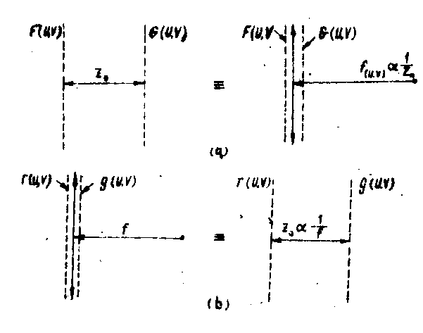
fig.2. a) the transfer function duality of propagators and lenses.
b) the impulse response duality.
we have found that lpm of the holographic processing introduces filters with the transfer characteristics of the type
 (1)
(1)
where x,y are the current space coordinates; u,v are the current courier spectrum
coordinates;  ; (p - f sin
θ;
θ = arcsin ( );
xr, yr=0, zr are the reference point coordinates;
z=0 equivalent to the hologram pla-
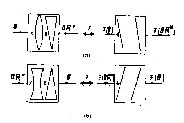
fig.3. a) transmitting lpm in space and apatial frequencies domains.
b) receiving lpm in space and spatial frequencies domains.
ne (fig.1); is the proportionality sign.
this filter produces a linear fm impulse response having the instantaneous frequencies
 ;
;  (2)
(2)
on the other hand the transfer function h(x,y) has the form of an "all-pass" with quadratic phases

 (3)
(3)
and linear group delays

 (4)
(4)
such a filter has some remarkable properties i.e. spatial compression, spectral analysis and Image formation. we shall make an analysis of these properties in connection with the holographic processing of information expressed by lpm.
the spatial compression in a holographic process is similar with the passive method for pulse compression used in chirp radar /1-3/ *). here the chirp signal is obtained by spatial propagation of the object wavefront and lpm serves as dispersive filter. with this underlaying analogy, we shall obtain some important quantitative results.
first, we consider the simple configuration of fig.1, supposing the path of reference and the object wave equally **) and the object wavefront spectrum rectangular envelope with the width l. we shall make our analysis in fourier space and all spectra will be denoted by a tilda (~) over the original functions. in accordance with the results exposed in refs. /1-2/ we have
 (5)
(5)
and
 (6)
(6)
the lpm output (the useful interference term) will be

 . (7)
. (7)
therefore the propagation has introduced a linear fm in the object spectrum envelope. if this envelope is large (paraxial object) in the holographic process, one obtains its compression. in this manner it is possible to obtain a high resolution processing of information.
f for estimating the efficiency of this processing it is interesting to calculate the spatial compression (dispersion) factor defined as
 (8)
(8)
where the area of central lobe of sin c function was considered aa compressed spectrum area. one can see that the compresaion factor depends on the reference point coordinates and on the object spectrum envelope dimensions. the parameters of lpm can be controlled and this factor must be made very high (d~104 in a practical configuration).
following our analysis of eq.(7) we can say that in the holographic process appears due to the spatial compression a light energy concentration (the envelope amplitude will increase by a factor l2, dependent on the envelope dimensions) which allows the registration of message at lower energy levels than in conventional photography. the compressed spectrum contains a residual linear fm, which occurs at the same rate, as in the "chirp" signal but is reversed in sense.
let us analyse now the reconstruction (detection) process.the impulse response of demodulating lpm is
 (9)
(9)
which produces an output
 (10)
(10)
with the same form as the object spectrum f(u,v). (it contains a residual phase shift only).
now we shall analyse the holographic processing of a general complex object wavefront. we consider that the object wavefront spectrum has the envelope a0(u,v) and an approximative linear instantaneous frequency, so this is
 (11)
(11)
with
α=f/2k and p=f sinθ.*) the output of a lpm with impulse response
 (12)
(12)
will be
 (13)
(13)
this result ie very important. it shows that the envelope of the object spectrum is transformed in the one side-band transfer of holographic process (modulating lpm) into its fourier transform shifted in function of fm properties and object phase) and the lpm response has a linear fm which occurs at the same rate but in reversed sense. therefore if the envelope of f(u,v) is large the envelope of compressed spectrum g(u,v) will be narrow, allowing a very efficient use of a given spatial bandwidth.
for the reconstruction process the impulse response of the demodulating lpm is
 (14)
(14)
which produces the output
 (15)
(15)
with the same form as for the object wavefront spectrum f(u,v).
we make here an important remark: in the above procer, the demodulating lpm appears as a matched filter for the comprwed chirp signal.
therefore in this process a maximum snr (ideally one) is expected. alternatively, this result can be found from the analy-
sis of the holografic process as a spatial heterodyne detection.
one can obtain an exact spectral analysis with lpm introducing some supplementary dual elements (propagators or lenses) for residual mf compensation (fig.4b with α=β=γ
). the essential relation has the form
 (16)
(16)
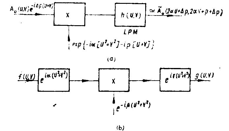
fig.4. a) the block-diagram of the approximate spectral analysis made with lpm.
b) the block-diagram of the exact spectral analysis and Image formation.
if in fig.4b we have α+γ=β (lens law), then another property of lpm can be shown: the Image fo
rmation (change of scale) /3/. in this case the essential relation is
 (17)
(17)
(using paraxial approximation).
eqs.(16) and (17) are not directly related to the holografic process and we finish here our analysis concerning lpm properties.
using lpm we can obtain a real time simulation of any kind of holographic process. this simulation can give us the data related to the optimum configuration and parameters of the hologra-
phic registration/reconstruction process for the efficient use of a given support.
the analog - deterministic bandwidth reduction in holography
we have seen until now that the envelope of the object wave-front spectrtum is compressed in the transfer to the one sideband of hologram. the analysis of the limitations introduced by the principal parameters of the hologram support shows that a further reduction of the hologram bandwidth leads to the decrease of snr and sbp. for all that we are interested in a futher reduction of the hologram bandwidth since we wish to achieve a matching with the present electro-optical systems. we must keep in mind that holography is not only the registration of a 3d wavefront, but also a simple method for information coding, very stable against perturbations, and using a matched filtering detection.
in 1965 e.n.leith et al. /4/ have proposed a 3d television system, in which real-time holograms were obtained and transmitted through tv channels. the principal difficulties of this system were the large spatial bandwidth for the small resolution of ithe hologram support (tv camera, large aperture photodetectors etc.) and the high rate for the transmission of htr data through the tv channel.
for solving the first difficulty we shall expose an analog-deterministic method for the spatial bandwidth reduction in holography by a factor of 8. this reduction is achieved joining 3 known methods of suppression of the redundant information (fig.5) /5,6/.
1. on-axis holography with temporal synthesis of reference (carrier) for conjugated terms separation /7-11/.
2. scanning hologram for elimination of the stationary terms (which have no interaction remaining at low frequency)*).
3. siligle side-band holography for a sideband elimination /12/ (ssb).
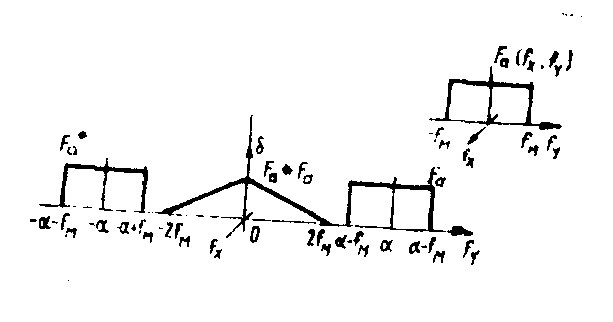
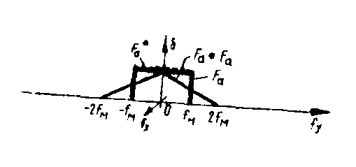
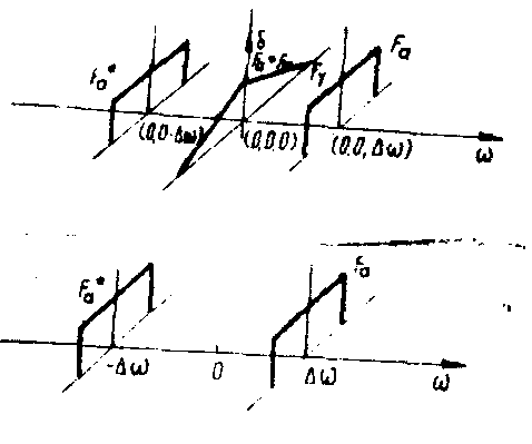
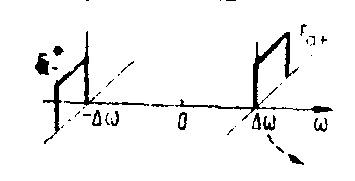
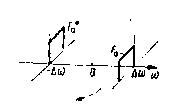
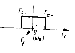
fig.5. the sequence of operations for the spatial bandwidth reduction in registration and for the object reconstruction.
each of these methods reduces the spatial bandwidth by a factor of 2, which gives a total reduction of sight through a suitable combination. this is a maximum analog-deterministic reduction due to the use of a ssb technique, but it can be improved by the use of supplementary statistical and/or digital optical systems.
a system joining the above mentioned techniques is illustrated in fig.6. the object wavefront, to be registered, is complex and the conjugated terms are not redundant. as a consequence the registration system has two channels corresponding to the right and left sidebands, respectively. the registration is made with an on-axis temporally shifted reference. the lens l1 performs a fourier transform and the knife-edges, introduced in both the right and left channels, in the fourier planes, cut the corresponding sidebands. the lenses l2 and l3, make another fourier transform in the photodetector plane, where we find the optical signal in the space domain. we shall consider the holographic registration on a tv camera (with electronic scanning ), although we can use a large aperture photodetector with an optical scanning, produced by a point reference*). fig.6 also shows two shutters acting sequentially for periods determined by tv receiver which reconstructe (detects) the Image.
in the reconstruction(detection) process (fig.7) we introduce an electrical carrier for the easier separation of the sidebands. after that, the term ir3 is electrically filtered and delayed with the switching time on the left channel (
Δ). the term ll3 is filtered and is introduced simultaneously with the delay ir3, at the adder input. the adder output gives the video current for the kinescope.
the mathematical treatment of this method is exposed in our paper /5/.
we shall remark that using the proposed method, the resolution requirements for the optical hardware are decreased by a factor of eight, which comes near the possibilities of the actual components /13/. our method could be employed together with
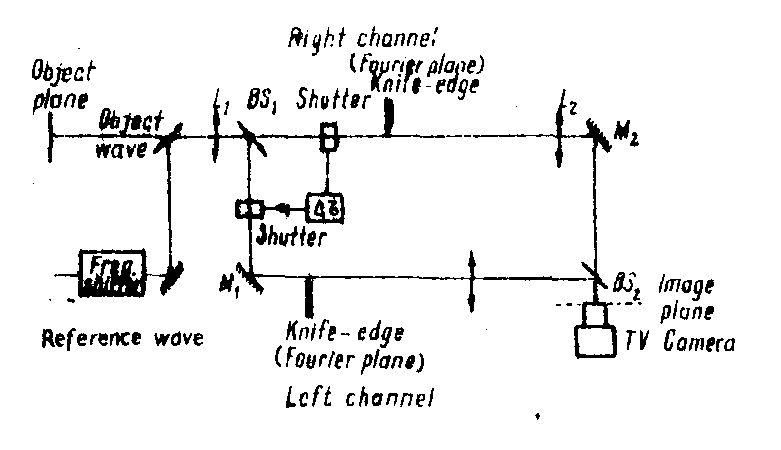
fig. 6. a configuration for registration of real-time holograms and for optical processing of information which saves the support resolution requirements by a factor of 8.
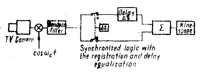
fig.7. the corresponding electrical processor for reconstruction (detection).
a statistic and/or digital processing for obtaining stronger bandwidth reduction and improved resolution performances.
now we shall show some possible applications of our method for obtaining real-time holograms with reduced apatial bandwidth in the optical processing of information.
first, we shall obsarve that the configuration given in fig.6 can be used for an optical filtering. we can introduce an optical filter with the transfer function h(fx,fy) in the fourier plane of every channel, near the knife-edges. in this situation the reference could be introduced after bs2. in the anterior analysis, h(fx,fy) appears in a product with object transfer function, in the inverse fourier transform. we can perform in this manner the removal of random noise from a periodic signal, the oontfaflt enhancement, etc. particularly, if
 (18)
(18)
the proposed configuration performs a matched filtering, in which the object autocorrelation and convolution can be registered separately (and transmitted through a tv channel). in this case the tv camera must resolve the entire object bandwidth, because the autocorrelation and the convolution have the double spatial bandwidth.
another possibility is the obtaining and displaying of the hilbert transform of the object impulse response. we shall suppose that the object impulse response o(x,y) has a hilbert transform h0(x,y) (i.e. it is the real or imaginary part of an analytic complex function) and, for simplicity, o(x,y) is real. in this case the light intensity which falls on the photodetector from the right channel (with the reference introduced after bs2) is
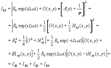 (19)
(19)
the left channel produces
 (20)
(20)
one separates ir3, and then it is delayed with
Δr and changed in sign; then, it is introduced together with ll3, in the adder. at the output we obtain the video current for the kinescope
 (21)
(21)
let us consider a phase object which introduces small phase shifts, that is
 (22)
(22)
following the same way, we shall obtain, now the video current
 (23)
(23)
if hφy(x,y) is sufficiently smooth and varies more slowly than y-2 (this is, we approximate y-2 by δ(y)), we can write
 (24)
(24)
then eq.(2.3) becomes
 (25)
(25)
which gives a display of the phase gradient in the y-direction. turning 90° the knife-edges, we can visualize the phase gradient in the x-direction. this is a very useful result for the display of the refraction index gradient of the transparent media (particularly in aerodynamics).
some experimental results for displaying acoustic and flow fields using optical heterodyne detection and some techniques for hologram bandwidth reduction can be found in our papers /5,6/. these results recommend the above system as an efficient ejectro-optical coupling to a real-time information processor.
obtaining real-time holograms
the importance of r.t.h. stems from their potential of integral use of the light carrier capacity, spatially and temporally. the light carrier can be transmitted over a certain distance limited by the channel and terminal parametars. then, one can imagine a rational multiplexing in the space and temporal domains. on the other hand, rth can be stored easily in photographic emulsions, photochromic materials, etc. the rth development is related to the research of new photosensitive materieils which would not require dead times for the processing steps after and/or before the exposure and consequently, would decrease the access times.
we shall present some materials and methods used in our experiments for obtaining rth and, clearly, the list will be not exaustives photoelectric sensor, photochronic materials, liquid crystals, photopolymers, and finally, nonlinear absorbers.
rth recording on photoelectric detectors was described in a suitable form in the section "the analog-deterministic bandwidth reduction in holography" and we do not reiterate it. we mention only some advantages of the photoelectric support; simplicity, use of some existing electronic techniqueis, good linearity, the possibility to simulate electronically the reference wavefront at reconstruction. difficulties: relatively small aperture, nonuniform sensitivity, and low resolution (~102 mm-1). the method for obtaining rth on photoelectric detectors uses generally a type of scanning and many times the model of heterodyne detection /6-8/.
the photochromic materials /14-20/ consist of organic molecular layers or anorganic substances inserted in crystals or glasses. they present two states with different orbital electronic structures and with different absorbtion bandwidths (usually, in u.v. and visible). the activation (recording) is done in u.v. and the read-out (demodulation) in visible (fig.8 a,b). the information can be erased by heat or irradiation in i.r. and the material is reversible (fig.8 c). the read-out is nondistructive (up to 104 cycles). there are no chemical, thermal, or electrical processing steps. the storage period reaches 1-80 hours.
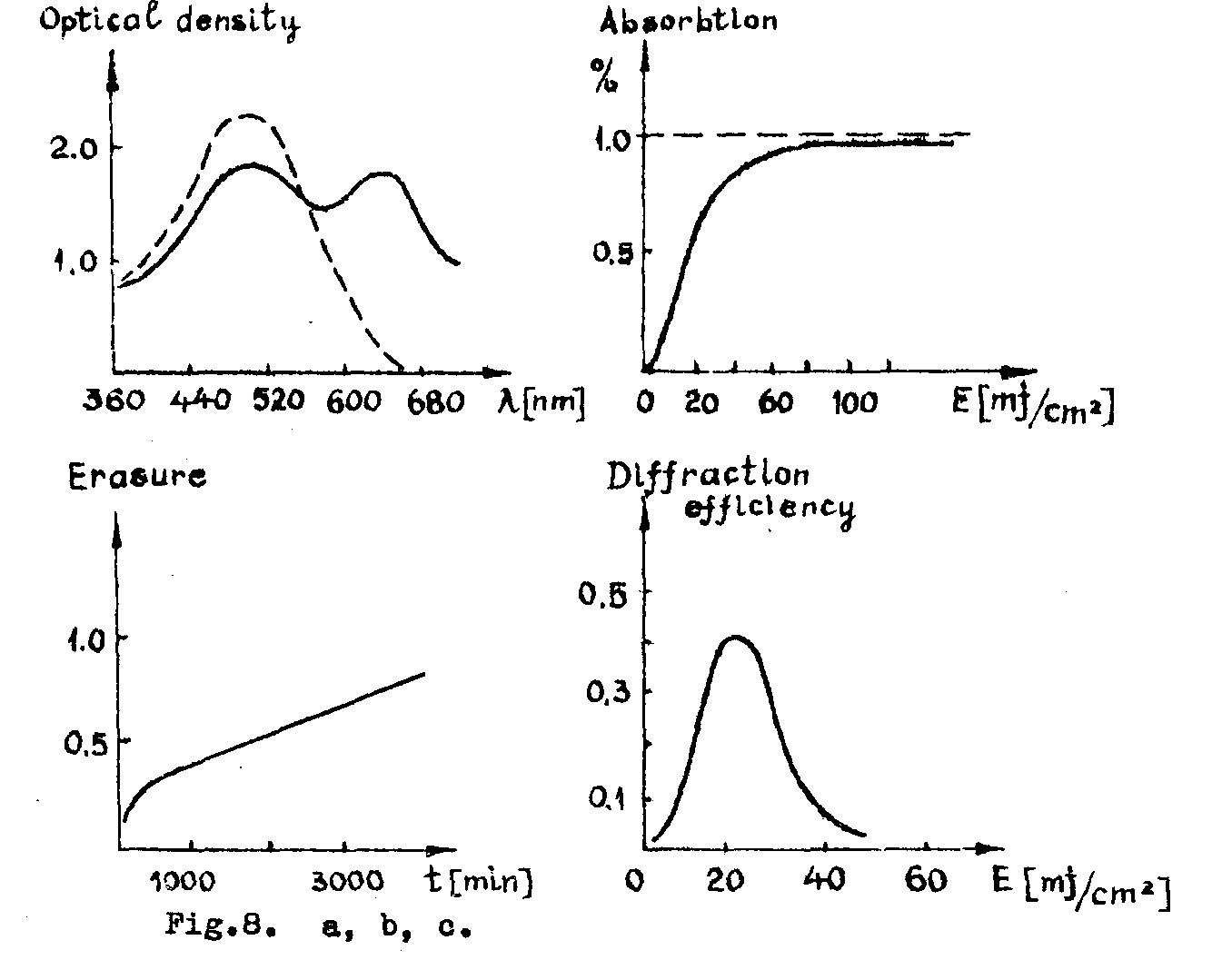
fig.8. a,b,c.
the photochromic materials show sometimes higher resolution than the photographic emulsions: 3000 mm-1, at a storage capacity of 105 bits/cm2 and time constants of 10-13 - 10-7 s. such materials are for example the single crystals of linbo3 /19/, caf2 /20/ etc.
recently, a photosensitive divitrification process in thin and thick films of arsenic-sulfur glass was used for obtaining rth /21,22/. for recording an argon laser (4880 Å, 10 mw/cm2, 10-15 min.) is used and the read-out is done with a he - ne laser (6328 Å). (fig.9 a). the diffraction efficiency can reach 18 % (fig.9 b) and the resolution was measured up to 3000 mm-1.
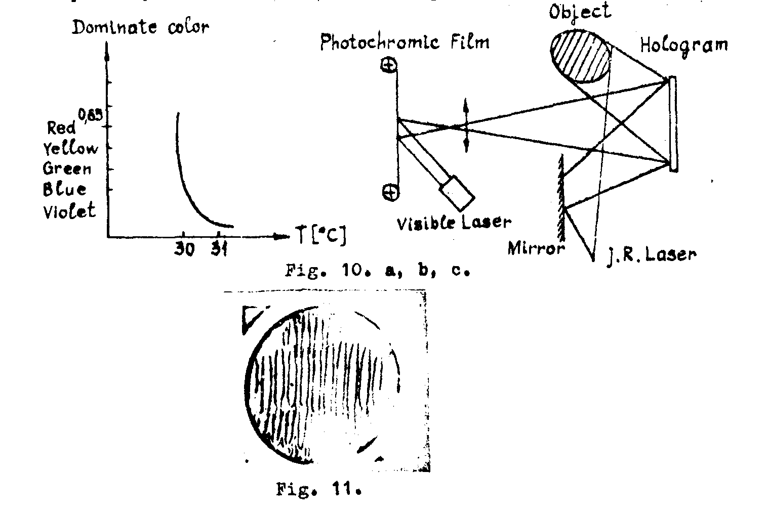
the liquid crystals /23-26/ are cholestheric compounds in common solvents which aew sensitive in a large spectral range (from i.r. to microwaves by thernal effect). under the thermal action, the molecula aggregate existing in the material get into a definite, oritintation which diffract only some wavelengths. (fig.11) (fig.10 a). there are some compounds which work in a large range
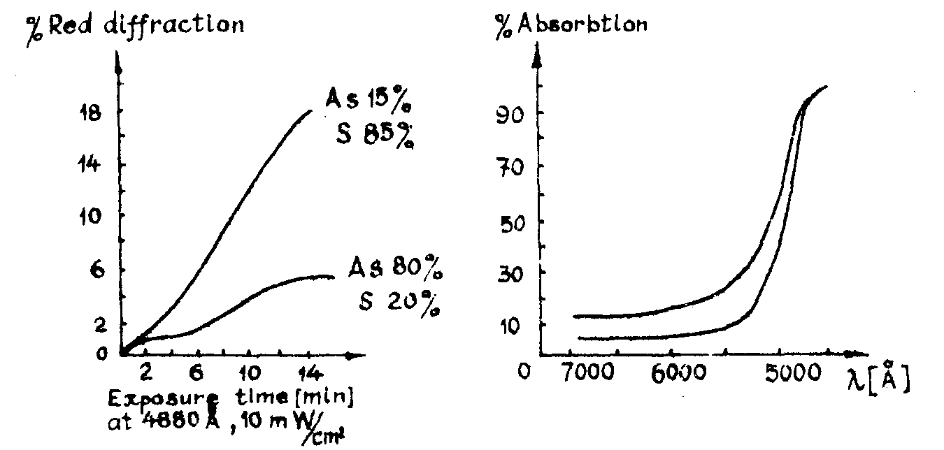
fig. 9. a, b.
of temperatures with a stable and precise effect. (
λ=10.6μ; 50 mw/cm2; 2 sec). other advantages of liquid crystal films are the reversibility (the erasure is done using an audiofrequency field) and the large detection area available with a near uniform sensitivity. the disadvantages are the low resolution (-20 mm
-1) and the low speed. a configuration for obtaining rth on liquid crystal films is shown in fig.10 b.
we must remark here that in i.r. there are a lot of materials which record rth: the gelatine h, spiropyrans /27,28/ liquid crystals, cu2hgi4 films /29/ etc. the experimental technique is invariant and very common for the obtaining rth: one records the hologram in i.r. (λ1), the hologram is reduced in the ratio λ2/λ1, and the read-out ia done in visible (λ2).
other type of photosensitive materials for obtaining rth are the photopolymers /30,31/. the recording operation consists of the photochemical induction of a radicalic chain reaction. the long polymer chain coupled by heavy metalic ions lead to the diffraction properties of recorded rth. one can obtain by this process phase hologram with efficiencies better than 30% (λ=6328 Å, 3 mj/cm2). (fig.12 a). the resolution could reach 3000 mm-1 (fig. 12 b,c,d).
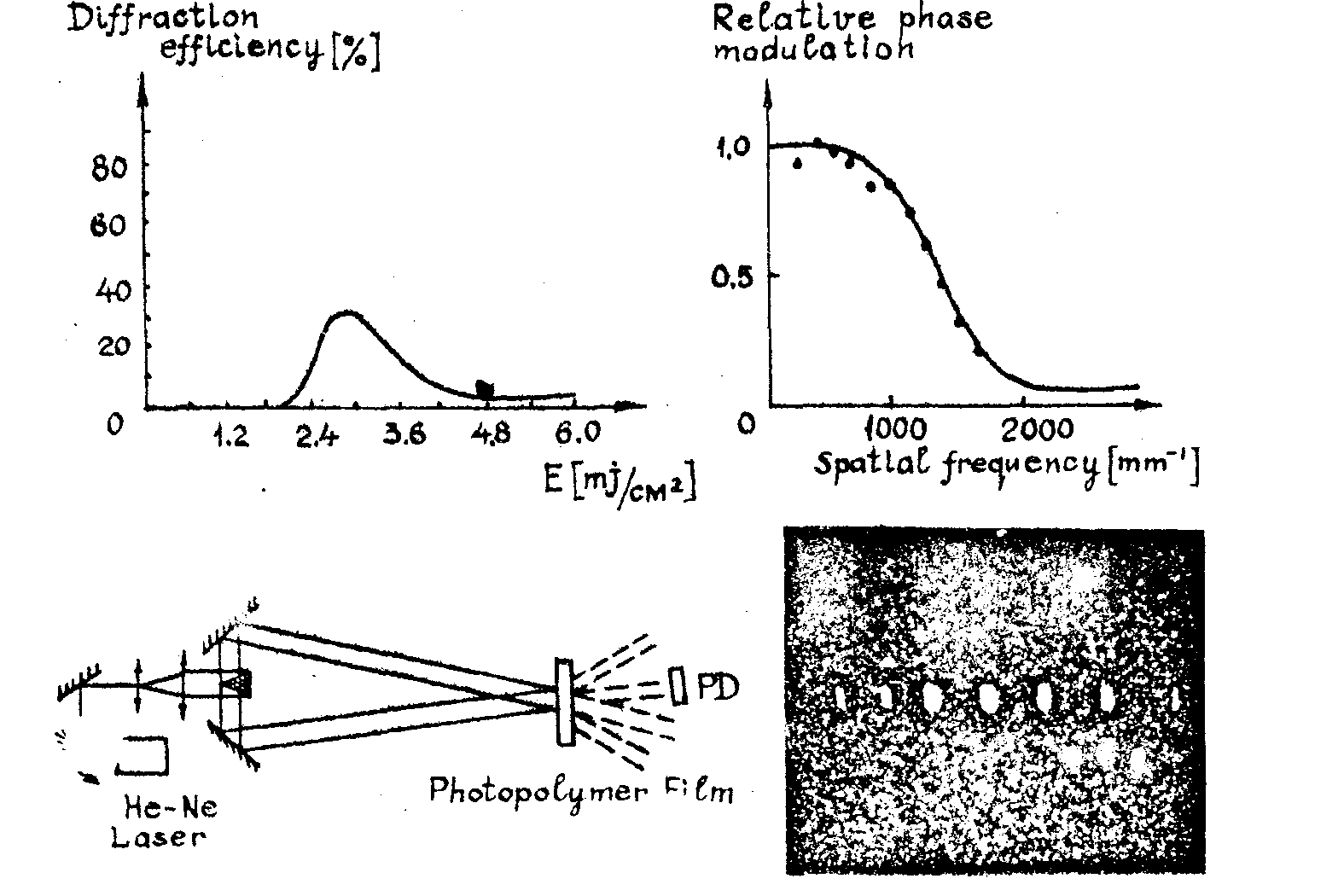
fig. 12. a, b, c, d.
the nonlinear absorbers /32-38/ are anorganic and organic substances which show a saturated absorbtion in a certain spectral
range. the q-switch and mode-locking operational have imposed a lot of dye, glasses, plastics, gases, etc, as nonlinear absorbers for all lager wavelengths. the sensitivity of some nonlinear absorbers appers to be comparable with the sensitivity of photographic emulsions. (table 1, fig.13). the senaitiyity can be expressed as function of the spectroscopic parameters of the nonlinear absorber /35/:
 (26)
(26)
where σ is the absorbtion cross-section at λ
, r is the time constant of the excited state, and t0 is the amplitude transmittance at low exposure levels.
table 1
|
material |
kodak 649 |
agfa 10e75 |
agfa 8e75 |
ciaipc metal-
free pc |
crypto-cyanite |
schott 715 |
|
sensitivity
erg/cm2
λ 0=6933Å |
104 |
2*102 |
2*103 |
8*103
(1.5 mm) |
105
(1.5 mm) |
4*104
(1 mm) |
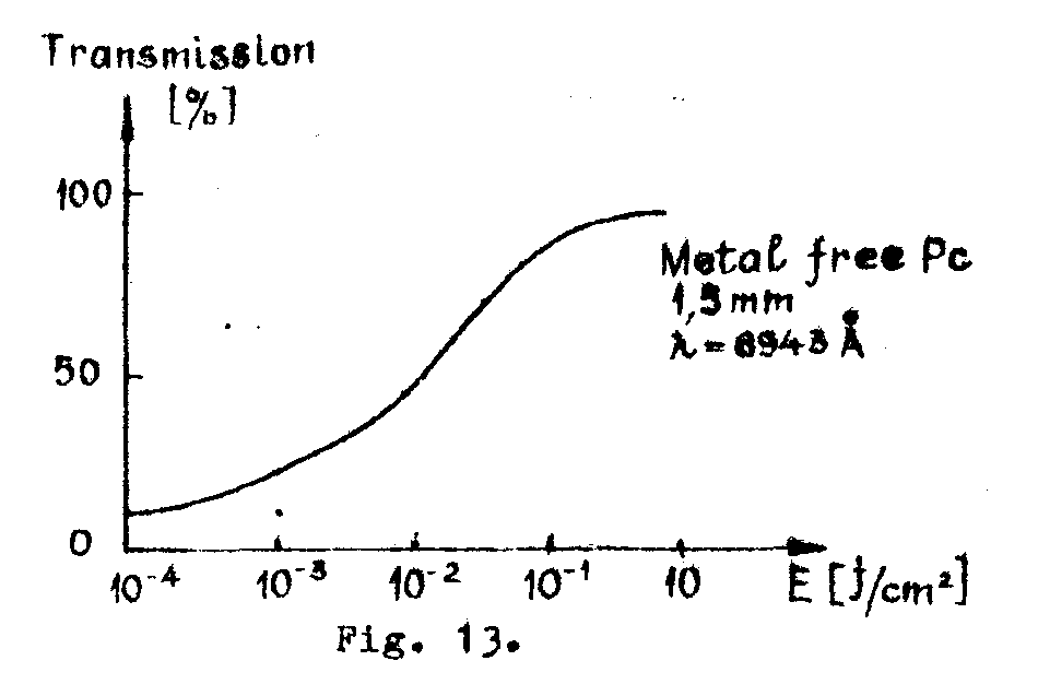
fig.13.
the resolution of the nonlinear absorbers seems to be very high (> 3000 mm-1) due to the recording by atomic and molecular processes. the diffraation efficiency is quite low (~ 1.56 %) for thin, absorbtion holograms but could be improved using thick, dielectric effects. (fig.14).
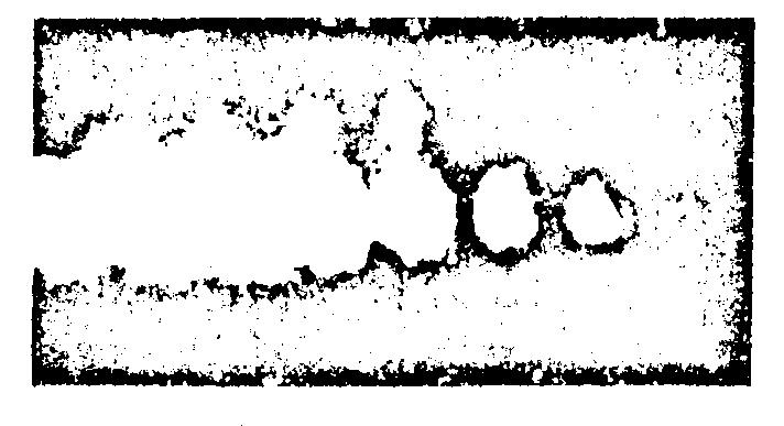
fig. 14.
a solution for the transmission of rth with reduced bandwidth could be the use of an underground lens waveguide for the phase distorsion and atmospheric perturbation suppression /35,36,39/. (fig.15). in this case, the principal perturbation of light beam is a slow displacement of the beam center due to the thermal gradients in the waveguide (which could be compensated even for
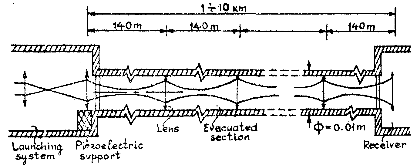
fig. 15.
distances of 10 km) and the waveguide attenuation reaches an acceptable value of 0.15 db/km. the mentioned perturbation produces variations of the spatial carrier frequency. this optical waveguide allows hifh rate transmission of the hologram data.
we shall observe that this method is very useful for a simple coded Image transmission with a good stability against the perturbations. we can use the light carrier in infrared and special registration technique (for example, diffusers).
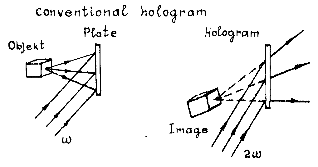
for a formal treatment of obtaining rth we could use at least two analogies: the spatial heterodyne detection /7, 36/, and the nonlinear Image conversion /38/. the last method is basically shown in fig.16.
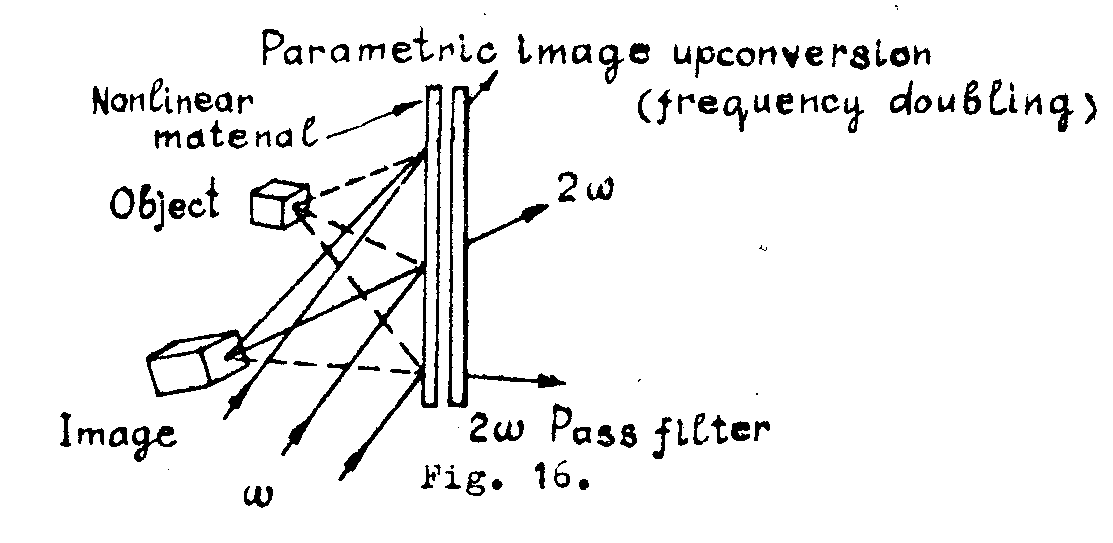
we have considered a frequency-doubling Image processor: the object beam frequency
ω and the reference beam frequency ωr are mixed in a nonlinear, isotropic, dispersionless material. the total field inside the material produces a nonlinear polarisation at the sum or difference frequency
(ω'=|ω±ωr|) which acts as a source for a parametric
radiated field at frequency ω'. the parametric generated Image is essentially identical to the vir -
tual Image when a conventional hologram is read-out by a reference at the parametric output frequency and along the same direction as the original reference beam. the difference stems in the fact that, in nonlinear optical Image conversion, exists only the term correaponding to a virtual orthoscopic Image and no others terms.
in this analogy the virtual Image undergoes an angular demagnification of one half; the transverse dimensions of the Image remain uncnanged. the location of the virtual Image ralative to the hologram medium and the longitudinal dimensions of the Image double in size. thus the virtual Image appears smaller because of the virtual Image will be shifted so that it is at half the angle that the original object made with the reference beam.
we finish here our analysis of the methods pertinent to the processing of information contained in a rth but we remark that there are many other ideas which have been used or are able to be applied in this field.
r e f e r e n c e s
1. v.i.vlad. proc.conf.holography and the computer,ibm-houston, (1969) si rev.roum.phys.,16, no.1,73, 1971.
2. v.i.vlad. metode de prelucrare a informateiei in holografia conventionala si timp real, teza de doctorat, ipb, buc., 1972.
3. a.papoulis. systems and transforms with appl.in optics. mc. graw-hill, n.y., 1968.
4. e.n.leith et al. j.s.m.p.t.e., 74, no.10, 893, 1965.
5. v.i.vlad. proc.conf."lasers and their appl." dresden (1970), si rev.roum.phys., 16, 855, 1971.
6. v.i.vlad. lucr.simp."domenii multidisciplinare si interdisciplinare", acad.r.s.r., apr.(1971), si in lucr.simp.int.telecomnunicatii, buc.,oct.,1971.
7. l.h.enloe et al., b.s.t.j., 47, no.9.1875, 1968.
8. c.b.burchardt si l.h.enloe. b.s.t.j., 1529, 1969.
9. a.b.larsen. b.s.t.j., 48, no.7, 2507, 1969.
10. iu.n.denisyuk & d.i.staselko. dokl.nauk ssr, 176, 127, 1967.
11. a.macovski. a.p.l., 14, no.5, 166, 1969.
12. o.bryngdhal & a.lohmann. j.o.s.a., 58, no.5, 620, 1968.
13. r.potter. optical proc.of int., eds.pollak, koester si tippett, spartan books, baltimore, md., 1963.
14. kirk. a.o., 5, 1684, 1966.
15. a.l.mikaeliane et al.ieee j., qe-4, 757, 1968.
16. s.herman.symp.on modern optics, p.i.b., 743, 1967.
17. z.j.kiss. ieee j. qe-5, no.1, 12, 1969.
18. v.a.tsekhomsky. optika i spektroskopia, 67, 1969.
19. j.la macchia. laser focus, febr., 35, 1970.
20. m.chomat, m.miller. tech.rept.inst.radioeng.electronics, c.a.s., prague, 1971.
21. r.g.brandes et al. a.o., 9, 1712, 1970.
22. laser weekly, january, 31, 1, 1972.
23. pergasson. acoustical holography, l.larmore et al., eds., vol.2. plenum press, n.y., 1969.
24. f.keilmann. a.o. 9, no.6, 1319. 1970.
25. g.h.heilmeier. proc.ieee, 57, no.1, 34, 1969.
26. c.f.augustine & w.e.kock. proc.ieee. no.5, 35, 1969.
27. t.izawa et al. a.p.l., 15, 201, 1969.
28. m.lescinski & miler. optics commun., 1, no.9, 17, 1970.
29. j.chivian et al., apl, 15, no.123, 1969.
30. j.d.margerum. photo sci.eng., 12, 177, 1968.
31. j.a.jenney. j.o.s.a., 60, 1155, 1970.
32.f.gires. ieee j., qe-2, no.9, 621, 1966.
33. m.hercher. ieee j., qe-4, no.11, 954, 1968.
34. h.j.gerritsen. a.p.l., 10, no.9, 239, 1967.
35. v.i.vlad. technical note, c.r.c.g.e.marcoussis, nov., 1969.
36. v.i.vlad. appl.de l'holographie" eds.viénot et al., besancon, juillet, 1970.
37. h.eichler & b.kluzowski. z.angew.phys., 28, h.6, 1970.
38. a.h.firester. j.appl.phys., 40, no.12, 4842, 1969.
39. b.gloge. b.s.t.j., 46, no.4, 721, 1967.

